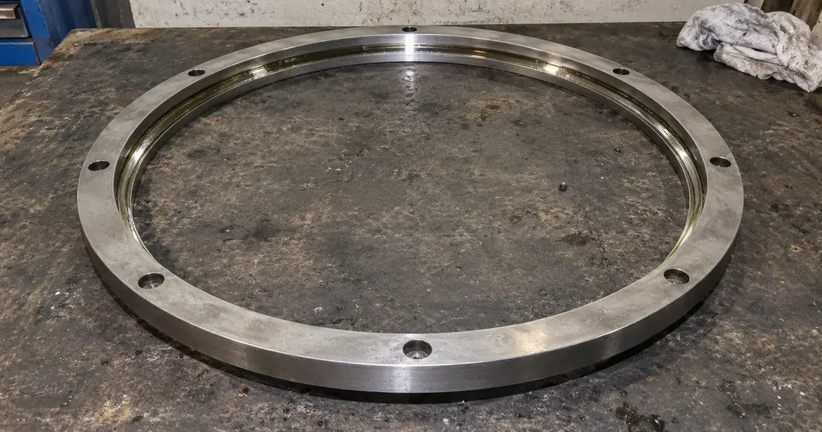
The ring is a metre across, weighs 91 kg, and turns at a fraction of a revolution per minute. The number that decides whether it survives is not in the load rating column.
That is the first surprise in specifying a slewing bearing, and there are three more behind it. The boundary dimensions answer to no standard, so the interchange you are relying on is a market convention rather than a specification. The type most people call the weaker one carries more static load than the type they reach for instead. And a large share of the failures trace to the weldment underneath rather than to the bearing. This guide works through the six types and the load diagram that actually sizes them. It then covers the two safety-factor systems in circulation, the gear and the bolt circle, and how to tell a worn ring from a badly mounted one. For the ratings vocabulary underneath all of it, start with our guide to dynamic and static load ratings.
Key Takeaways
- There is no dimension standard. SKF states that the boundary dimensions of its four-point ball and crossed roller slewing bearings comply with no international or national standard. Its light and medium series are nonetheless dimensionally interchangeable with competitors' products.
- Size on the diagram, not the rating. Every slewing bearing carries a static limiting load diagram with two curves: a solid raceway capacity curve and a dashed bolting capacity curve. The duty point has to fall below both. C and C₀ only get you to the right page of the catalogue.
- Multiply the load first. SKF applies an application load factor from 1.15 for turntables to 2 for compactors and carrousels. Kaydon applies a service factor from 1.00 to 1.50, keyed to duty instead of machine type. It adds a rule SKF has no equivalent of: maximum thrust rating should exceed three times maximum operating thrust.
- Balls are not the weaker choice. At a matched 1,094 mm mean raceway diameter, SKF's four-point ball rates C₀ = 2,710 kN against 1,450 kN for crossed roller, at identical mass. The roller version buys stiffness, running accuracy and zero clearance, and costs you speed.
- The support structure is part of the bearing. Machining is mandatory at Ra 3.2 to 6.3 µm, and overall flatness is capped at (dₘ + 1000)/10000 mm. The mounting flange wants a thickness of 0.03 to 0.05 × dₘ. A low-section ring takes the shape of whatever you bolt it to.
- The marks are mounting instructions. A red mark and the letter F locate the soft zone, the unhardened arc where induction hardening starts and stops. On assembly the two rings' F marks go 180° apart.
- Wear is measured, not guessed. Record axial tilting clearance at installation, then recheck after 2,000 operating hours or at least annually.
What Makes a Slewing Bearing Different From a Large Ball Bearing?
A slewing bearing takes axial load, radial load and tilting moment simultaneously, in any direction, and it replaces a pivot assembly rather than sitting inside one. That is the functional difference. It can slew, meaning oscillate through a limited angle, as readily as it can rotate (SKF).
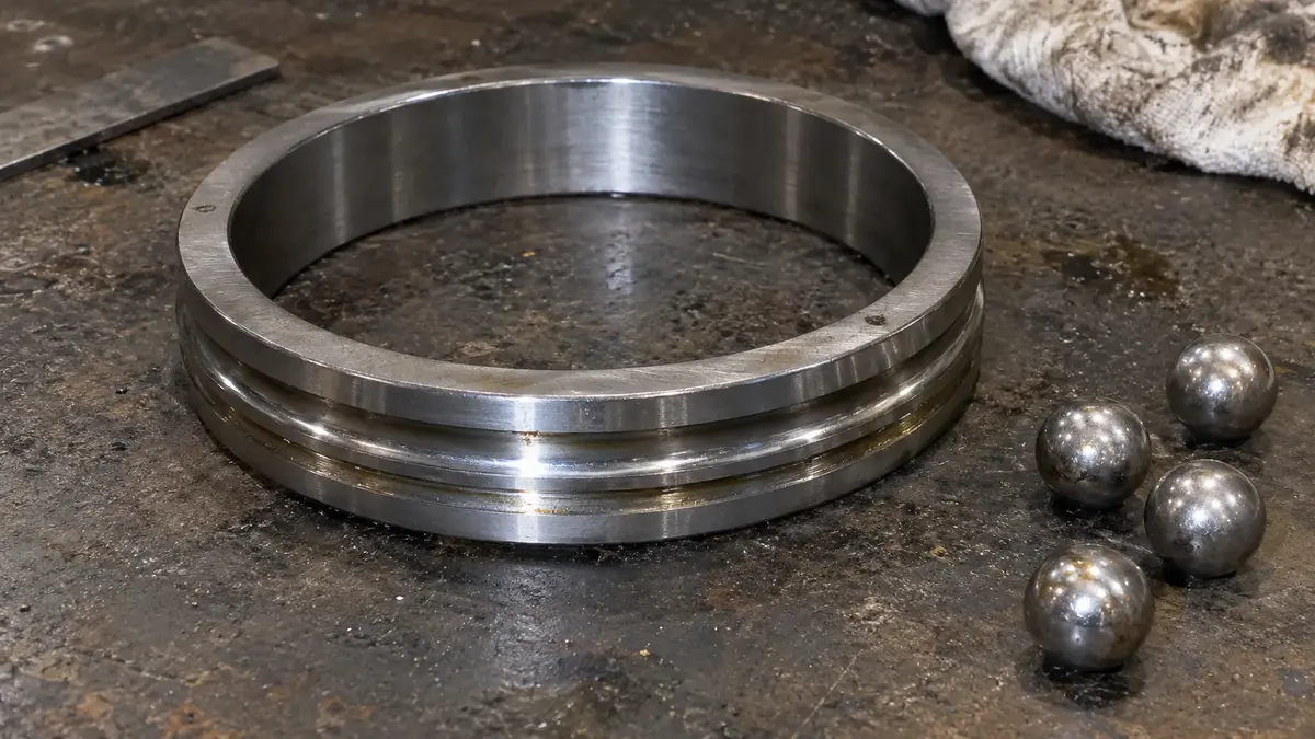
The construction follows from that job. An inner ring and an outer ring carry balls or cylindrical rollers separated by polyamide spacers rather than a one-piece cage. One ring usually carries a gear. Both carry holes, plain or threaded, for attachment bolts. Only the raceways are hardened and precision-ground, which leaves the rest of the ring, including the gear teeth, in its tempered condition. Integral seals in acrylonitrile-butadiene rubber keep grease in and contamination out, and grease fittings allow relubrication in service.
Two consequences matter at the design stage. The large bore and low sectional height simplify everything around the bearing, and in most cases the mating components need nothing more than flat machined faces. The same low section means the ring has very little rigidity of its own relative to its diameter. That is why the catalogue publishes tolerances for your weldment and not only for the bearing.
The size range is wider than most bearing families. SKF builds one-piece rings from 50 to 7,900 mm outside diameter, and segmented rings up to 14,000 mm. Everything published about capacity applies to supported arrangements, where the load presses the bearing down onto its structure. Suspended arrangements, where the bearing hangs, are referred back to application engineering.
What Are the Six Types of Slewing Bearing?
Single row four-point contact ball and single row crossed cylindrical roller cover the great majority of arrangements. The other four exist because a specific constraint on stiffness, capacity or mass defeats the two singles.
| Type | What it is for | Design notes |
|---|---|---|
| Single row four-point contact ball | Light to medium axial, radial and moment load. The most widely used type, and the cost-effective default | One-piece rings, polyamide spacers, balls loaded through a plugged hole |
| Single row crossed cylindrical roller | Heavy radial and medium axial load, where stiffness, running accuracy or zero clearance matters | Adjacent roller axes at 90°. Needs tighter support flatness and stiffness than the ball type |
| Double row four-point ball | Where the surrounding structure cannot deliver the stiffness or accuracy other types need | Normally preloaded. Full complement, window-type steel cage, or polyamide spacers |
| Double row cylindrical roller | Heavy axial and radial load with high tilting moment | Two independent roller rows loaded through two plugged holes. Normally preloaded |
| Triple row roller | The heaviest duty. Highest available load ratings | Two axial roller sets plus one radial set, polyamide cages, not preloaded. Sensitive to deflection of the surrounding structure |
| Wire race | Lightweight precision work with significant tilting moment | Aluminium rings with four through-hardened bearing steel wire inserts. Relatively insensitive to support surface imperfections |
Two entries on that table deserve a warning label. Triple row roller bearings give the highest ratings and are the least forgiving. SKF notes they are sensitive to the deflections of associated components, so an extremely stiff and accurately manufactured support structure is needed to reach maximum service life. Buying the highest rating and bolting it to a flexible frame throws the rating away. NSK's metals range is built on the same triple-row design, at 1 to 6 m outside diameter with internal, external or no gearing (NSK).
Wire race bearings carry a published weight saving that has moved. The 2019 catalogue puts single row wire race bearings at 70% lighter than similarly sized all-steel bearings. The current skf.com product page says 60% lighter (SKF). Both are SKF's figures for the same comparison, so treat the newer page as current and quote it with its date rather than splitting the difference. That page also carries SKF's claim for the eight-point contact ball design: an 80% capacity increase over a same-sized single row four-point contact ball bearing. That is the manufacturer's own comparison, not a measured result.
Ball or Crossed Roller? The Catalogue Disagrees With the Consensus
At the same mean raceway diameter and the same mass, the four-point ball slewing bearing carries the higher axial static rating. Not the crossed roller.
Four rows from one catalogue, all at a mean raceway diameter of 1,094 mm, settle it (SKF):
| Designation | Type | Element | C (kN) | C₀ (kN) | Mass (kg) |
|---|---|---|---|---|---|
| RKS.062.20.1094 | Four-point ball, internal gear | 20 mm ball | 303 | 2,710 | 91 |
| RKS.162.14.1094 | Crossed roller, internal gear | 14 mm roller | 279 | 1,450 | 91 |
| RKS.060.20.1094 | Four-point ball, no gear | 20 mm ball | 303 | 2,710 | 77 |
| RKS.160.14.1094 | Crossed roller, no gear | 14 mm roller | 279 | 1,450 | 77 |
Same diameter, same gear option, same mass to the kilogram, and the ball version carries 87% more static axial load and 9% more dynamic. That percentage is our arithmetic on the two catalogue rows, not a published figure.
So what does the crossed roller actually buy? SKF is specific, and none of it is capacity. When preloaded, the large roller-to-raceway contact area gives a high degree of stiffness and high running accuracy, which is why it is chosen where accurate positioning is a key operational parameter. It is also the type to specify when zero operational clearance or preload is required, or when a constant resistance to rotation matters.
The bill for that comes in four parts.
- Speed. Four-point ball bearings generate less friction and so run faster. Medium size ball reaches 4 m/s circumferential speed and the light series 2 m/s, while crossed roller is limited to 1.5 m/s continuous and 2 m/s for brief periods.
- Support tolerance. Crossed roller requires tighter specifications for support surface flatness and stiffness than four-point ball.
- Dimensional interchange. Four-point light and medium series are dimensionally interchangeable with competitors' products. For crossed roller, SKF states interchangeability only up to and including a 1,094 mm mean raceway diameter.
- Diameter tolerance runs the other way. Crossed roller holds ±1 mm on the ungeared inner or outer diameter across every size band. Four-point ball runs ±2.5 mm to 1,000 mm, ±3.5 mm to 2,000 mm, and ±5 mm to 2,500 mm. Total height is ±1 mm on both.
SKF's own selection guide marks crossed roller as recommended for running accuracy and not recommended for high speed, and marks the light ball series as not recommended for running accuracy. Read as a decision rule: pick the roller when the machine has to know where it is, and the ball when it has to move and carry.
The four contact points in that first raceway design are the same gothic arch geometry described in our guide to angular contact ball bearings, scaled to a metre of diameter.
Why C₀ Will Not Size a Slewing Bearing
A slewing bearing is selected by plotting a point, not by comparing a rating. Reduce the machine to one resulting axial load and one resulting tilting moment. Multiply both by an application factor, then confirm the point falls below both curves of that bearing's static limiting load diagram.
The load case comes first. SKF gives it as a pair of equations for the arrangement in its figure. The axial load is Fₐ = Qₐ + G₁ + G₂ + G₃. The tilting moment is Mₜ = Qₐ × L + Fᵣ × Hᵣ + G₃ × L₃ − G₁ × L₁ − G₂ × L₂. Here Qₐ is the lifting load, the G terms are weight fractions such as counterweight, cabin and boom, and the L and H terms are their lever arms. Where the working radii vary, the maximum radii have to be used.
Two rules then decide whether radial load matters at all. External radial load may be neglected while it stays at or below 5% of the axial load. If it acts anywhere other than the plane of the bearing, the resulting tilting moment must be calculated and carried. And if the ratio Fᵣ/Fₐ exceeds 0.6, SKF advises contacting application engineering rather than reading a curve. On combining the two force components into one load case in general, see axial versus radial load.
Then the multiplier. Both the axial load and the tilting moment are multiplied by the same application load factor, Fₐᵣ = fL × Fₐ and Mₜᵣ = fL × Mₜ.
| Application | Load factor fL | Application | Load factor fL |
|---|---|---|---|
| Handling workshops | 1.15 | Sedimentation tanks | 1.25 |
| Turntables | 1.15 | Aerial platforms | 1.33 |
| Welding positioners | 1.15 | Cement mixers | 1.33 |
| Concrete pumps | 1.5 | Mini excavators | 1.33 |
| Mobile cranes | 1.5 | Service cranes | 1.33 |
| Carrousels | 2 | Compactors | 2 |
The diagram is the last step and the one competitors skip. Each bearing in the product tables has a static limiting load diagram carrying two curves. The solid line is raceway capacity, defined as the maximum static load the bearing accommodates without detrimental effects on its running behaviour. The dashed line is bolting capacity, and it is specific to the fasteners. It assumes a supported arrangement, the stated number of grade 10.9 bolts anchoring that bearing, threads coated in a thin layer of light oil, and the catalogue tightening torque. The point where the rated axial load and rated tilting moment intersect must sit below both.
SKF's own worked example is short enough to run in full, and it is the thing most readers arrive looking for. A mini excavator needs a slewing bearing with an internal gear. Axial load Fₐ = 65 kN, external radial load Fᵣ = 12 kN, tilting moment Mₜ = 120 kNm. The load ratio Fᵣ/Fₐ = 12/65 = 0.184, comfortably inside the 0.6 limit, so any series qualifies on that count. With fL = 1.33 for a mini excavator, Fₐᵣ = 1.33 × 65 = 87 kN and Mₜᵣ = 1.33 × 120 = 160 kNm. Both RKS.062.20.1094 and RKS.162.14.1094 clear the diagram. Where stiffness matters, take the crossed roller. Otherwise the ball bearing does the job.
Note what did the work there. The 87 kN and 160 kNm are not compared against C₀ at all. Our guide to dynamic and static load ratings lists sizing a slewing ring on C instead of C₀ as the first common mistake. The numbers above are why: slow-rotating rings fail by raceway brinelling long before fatigue accumulates. The static ratings themselves are defined by ISO 76 and the dynamic ones by ISO 281, and both are quoted in the product tables. They are the sorting key, not the acceptance test.
SKF's Load Factor and Kaydon's Service Factor Are Not the Same Number
Two major manufacturers publish selection methods that multiply different quantities by differently derived factors. Moving a design from one supplier's curve to the other's silently changes the margin you thought you had.
| SKF load factor fL | Kaydon service factor SF | |
|---|---|---|
| Applied to | Axial load and tilting moment | The resultant bearing forces |
| Keyed to | Machine type | Duty within a machine type |
| Range | 1.15 to 2 | 1.00 to 1.50 |
| Radial load boundary | Neglect below 5% of axial; consult above Fᵣ/Fₐ = 0.6 | "Radial load less than 10% of the thrust load" defines a normal application |
| Extra margin rule | None stated | Maximum thrust rating should exceed 3× maximum operating thrust |
Kaydon's table splits by how the machine is worked rather than what it is. A tire-mounted mobile crane on normal construction duty takes 1.00, the crawler-mounted version 1.10, the same crane on scrap and ship-yard production duty 1.25, and forestry handling 1.50. Excavators split by what limits the load: 1.25 where tipping limits it, 1.50 where hydraulic pressure relief does. Index and turnstile tables run 1.00 to 1.50 on frequency and impact, and steering gear takes 1.25 on pneumatic tires against 1.50 on solid ones (Kaydon).
Compare that with SKF's list and the disagreement is real rather than cosmetic. SKF gives mobile cranes a flat 1.5. Kaydon gives the same machine anything from 1.00 to 1.50 depending on what it lifts all day. Neither is wrong. They are different abstractions, and a designer who carries a factor across without re-deriving it is applying a number that was calibrated against a different curve.
The thrust margin is the sharper difference. Kaydon states that the maximum thrust rating should exceed three times the maximum operating thrust force, whatever the moment at that condition. The reasons given are structural rigidity and load distribution. SKF's method contains no equivalent, because its bolting capacity curve absorbs part of the same concern. If you size to SKF's diagram and then quote a Kaydon part on the same duty, check the 3× rule separately.
The speed limits are worth converting, because the two makers use different units and land in an interesting place. Kaydon's normal-application ceiling is 500 fpm for single row bearings and 300 fpm for multi-row. At 0.3048 m per foot that is 2.54 m/s and 1.52 m/s. Kaydon's multi-row figure sits within rounding of SKF's 1.5 m/s crossed roller limit, while its single-row figure is well below SKF's 4 m/s for a medium size ball bearing. The two houses agree closely on the roller and multi-row ceiling and diverge by a factor of about 1.6 on single row ball. Those conversions are ours; the source figures are Kaydon's.
Kaydon's definition of a normal application is a useful pre-flight list in its own right. It assumes a vertical axis of rotation, compressive thrust and moment loading, and radial load under 10% of thrust. It also assumes oscillation or intermittent rotation, an operating temperature within −20 °F to +140 °F (−29 to +60 °C), proper installation, periodic lubrication, and periodic confirmation of bolt tension. Fall outside any of those and the published curve is no longer the whole answer.
What Actually Caps the Operating Temperature
The ring steel is not the limit. The polyamide spacers, the rubber seals and the grease are, and SKF's published window for the catalogue range is −25 to +70 °C.
The standard fill is a mineral oil grease with a lithium soap thickener and extreme pressure additives, at NLGI consistency 2. Base oil viscosity is 200 mm²/s at 40 °C and 16 mm²/s at 100 °C. Reliable lubrication on SKF's traffic light concept sits between +30 and +110 °C, which is a narrower and more useful statement than the grease's own range. On how base oil viscosity and additive chemistry drive that choice, see our guide to bearing lubrication.
One thermal trap deserves naming, because it is easy to design in. If the outer ring runs cooler than the inner ring, internal clearance falls or preload rises. SKF flags this as a reason to consult application engineering, and it is exactly the condition created by a hot hub inside a ring exposed to ambient air.
The practical lubrication rules are short and unusually forgiving, because these bearings turn slowly:
- The free space between the rings can be filled entirely with grease.
- Grease immediately after mounting, until fresh grease escapes from the seals around the whole circumference.
- Relubricate while the bearing is turning, so the grease distributes.
- Relubricate through four equally spaced cone type grease fittings to DIN 71412:1987, design A, in the inner ring on externally geared bearings and the outer ring otherwise.
- Relubrication intervals come off a diagram against operating hours per week, valid at a 70 °C operating temperature with good grease. Dirt, damp or higher temperature shortens it.
The gear is lubricated separately and ships preserved rather than greased. Its lubricant needs a base oil viscosity of at least 500 mm²/s at 40 °C, good adhesion, high resistance to water washout, and tolerance of at least +100 °C.
Integral seals are not a substitute for external protection. SKF is explicit that they are not intended for bearings exposed to water, vacuum, high levels of abrasive contaminant or radiation. A commercially available large V-ring, or a sheet steel cover bolted to the rotating or stationary part, is the usual secondary seal. Sealing as a specification lever in general is covered in sealed versus shielded bearings.
The Gear: Why the Teeth Are Deliberately Soft
The integral gear is a 20° involute cylindrical gear, and it is not hardened. SKF cuts it to a house specification that closely follows accuracy grade 12 of ISO 1328-2, and rates it with two separate tooth forces rather than one.
That pair of ratings is the part worth understanding. Tf normal is the tangential tooth force for normal operating loads, based on fatigue stress at the tooth base and calculated for 3,000,000 operating cycles. Tf max is the maximum permissible tangential force, based on fracture at the tooth base. Both are published per designation and both are valid for unhardened gears. A duty cycle that spends most of its life below Tf normal and touches Tf max occasionally is a different design case from one that lives near either limit. One number could not express that.
Gear position is a design decision rather than a preference, and it shows up in the designation. On SKF's medium four-point ball range, 061 is external gear, 062 internal, and 060 ungeared. The pinion contacts at the largest distance from centre on an external gear and the shortest on an internal one, which changes the lever arm the drive sees.
Backlash has published values and a counterintuitive floor.
| Module over | to and including | Minimum backlash | Maximum |
|---|---|---|---|
| 3.15 mm | 6.3 mm | 0.25 mm | 0.375 mm |
| 6.3 mm | 10 mm | 0.3 mm | 0.45 mm |
| 10 mm | 12.5 mm | 0.45 mm | 0.675 mm |
| 12.5 mm | 16 mm | 0.6 mm | 0.9 mm |
| 16 mm | 20 mm | 0.8 mm | 1.2 mm |
| 20 mm | 25 mm | 1 mm | 1.5 mm |
Measure it at the blue mark and the letter B, which locate the point on the circumference where the tooth gap is smallest, with a feeler gauge, after the pinion is positioned. Higher backlash elsewhere on the circumference is normal form tolerance and has no negative impact. And zero backlash is a fault, not precision: SKF states that practical experience has shown zero backlash can produce structural overloads that significantly reduce gear life.
The pinion carries the hardness the ring gives up. It is normally hardened and ground, and should extend past the bearing gear by roughly 5 mm on both sides. It also wants a tip relief of 0.01 × module, with a relief height of 0.4 to 0.6 × module and a radius of 0.1 to 0.15 × module. That relief exists to avoid meshing interference at the tooth root of the softer bearing gear. Where it is missing, the resulting run-in wear shows up as increased noise, which SKF describes as not really harmful: the wear rate falls progressively and the noise level should decrease. Distinguishing that run-in from a genuine bearing fault is the subject of our guide to bearing noise.
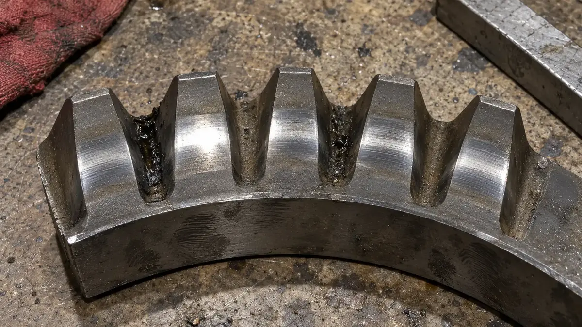
Teeth cut like that stay in the tempered condition, so what you see on them is a machining finish and not a ground one.
Mounting: The Support Structure Is Part of the Bearing
A slewing bearing has limited rigidity because its cross section is small relative to its diameter. It takes the shape of whatever it is bolted to. That is why the catalogue publishes tolerances for the fabricator's work, and why those tolerances are tighter than most weld shops expect.
Structure. The mounting flange must support the bearing ring across its entire side face. Minimum thickness is 0.05 × dₘ for a mean raceway diameter up to 500 mm, 0.04 × dₘ from 500 to 1,000 mm, and 0.03 × dₘ above 1,000 mm. Minimum wall thickness of the structure follows as S₁ = 0.35 × S. Thick-walled cylindrical structures with an inside or outside flange give better results than thin-walled fabrications with a trussed frame. The sub- and superstructure walls should line up with the rolling element assembly, so the load path stays direct.
Surface. Machining is mandatory, roughness should fall within Ra 3.2 to 6.3 µm, and the faces must be flat and free of rust, paint and burrs. They also need to be washed and dried, and specifically not left coated with preservative, oil or grease. The joint between ring and structure is a frictional one, and lubricating it defeats it.
Flatness, in three separate checks:
- Overall flatness in the circumferential direction is limited to tc = (dₘ + 1000)/10000 mm.
- Measuring points must be spaced no further apart than the attachment bolt hole pitch. Between two consecutive points, deviations in the same direction should not exceed 0.0002 × n, where n is the distance between them. Where the inclination changes direction, the sum of the two deviations should not exceed 0.002 × n.
- Flatness in the radial or transverse direction, the conicity across the width of the support surface, is limited to tt = B/1000, where B is that width.
Bolting, where the two manufacturers diverge again. SKF specifies hexagon head bolts to DIN EN ISO 4014:1999 in strength grade 10.9 (EN ISO 898), with a minimum bolt joint length of _L_K = 5 × G. Flat washers under both head and nut must be hardened or quenched and tempered, and spring washers of any type must never be used. Tightening runs in at least two stages with an accurate torque wrench or a hydraulic tensioner.
| Bolt size | Tightening torque (µ = 0.14) | Assembly preload | Preload at 90% of yield |
|---|---|---|---|
| M12 | 115 Nm | 56 kN | — |
| M16 | 285 Nm | 106 kN | — |
| M20 | 560 Nm | 166 kN | — |
| M24 | 970 Nm | 239 kN | 283 kN |
| M30 | 1,930 Nm | 385 kN | 454 kN |
| M36 | 3,380 Nm | 560 kN | 664 kN |
Kaydon accepts SAE J429 Grade 8 or ISO 898-1 Class 10.9. It tensions in three stages at 30%, 80% and 100% of the equipment designer's final design tension, in a star pattern. It also warns against thin riser plates under the bearing (Kaydon). Its flatness and deflection limits are published as graphs against pitch diameter and ball diameter rather than as formulas. That is a good reason to keep SKF's closed-form values to hand even when the part is not SKF's.
The soft zone is worth dwelling on. Only the raceways are induction hardened, and induction hardening has to start and stop somewhere. That leaves a small unhardened arc, which SKF locates with a red mark and the letter F. Wherever possible it coincides with the hole used to load the balls or rollers, closed afterwards with a plug shaped to the raceway contour. When the second structure goes on, the free ring's F mark must sit 180° from the mounted ring's F mark. Naming is not universal: many Chinese and aftermarket rings mark the same feature S. Same feature, different letter, and a reader who only knows one convention will look for a mark that is not there. Orientation marks carrying real assembly information is a pattern we have documented before, in four-row cylindrical roller bearings.
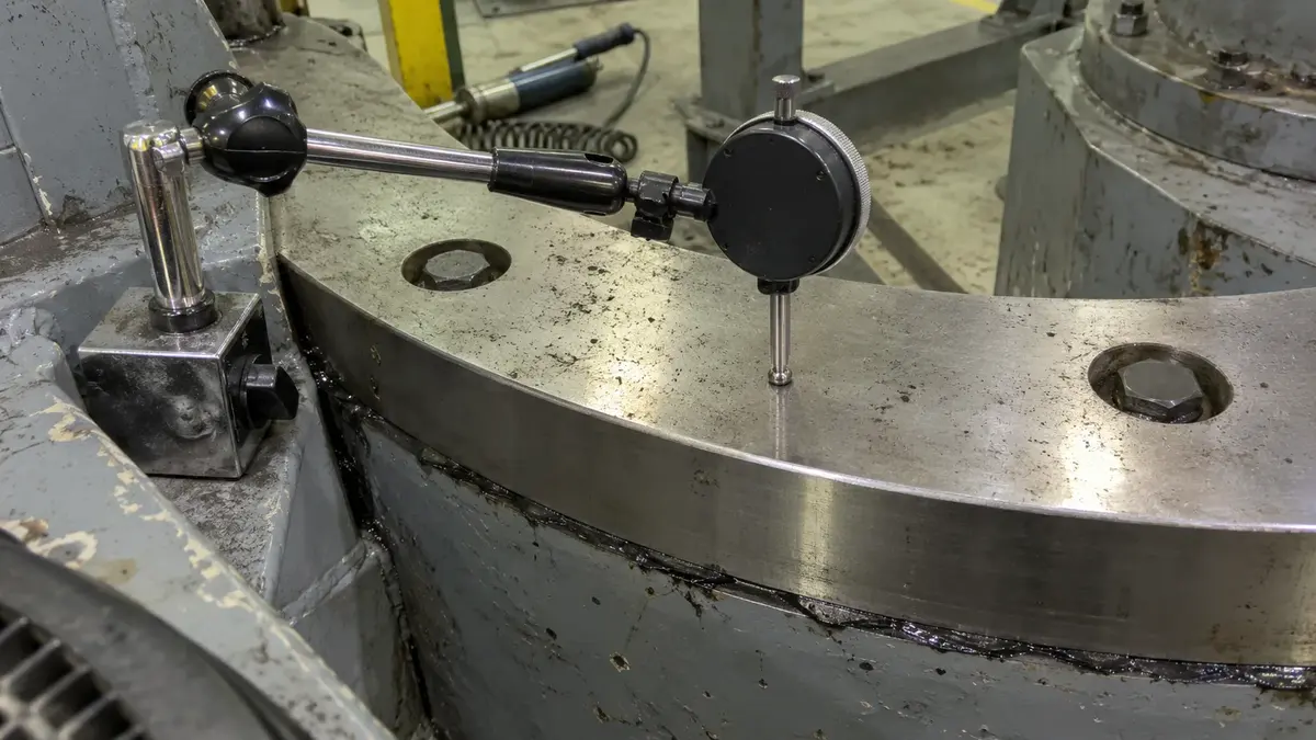
Two acceptance checks close out the installation. Rotate the free ring and confirm the torque shows no excessive variation or tight spots. High absolute torque from preload, grease and seal friction is expected; variation is not, and points at ovality. Then measure the axial tilting clearance in the main load line with a dial gauge, under a defined tilting moment. Confirm the radial clearance is virtually zero at 180° from the measuring point. Mark the measuring points on the adjacent component, and record the value on the installation report. That recorded number is the wear baseline for the rest of the machine's life, and it cannot be reconstructed later.
Rings above a 2,000 mm mean raceway diameter carry a black mark and get one extra step. Align the black marks, measure ovality at six points on 30° intervals on the centring diameters, and hold it within 0.5 mm for a mean raceway diameter between 2,000 and 3,000 mm. Correction is by small elastic deformation with jacks or a star shaped tool, not by force.
How Do You Tell a Worn Ring From a Badly Mounted One?
By comparing today's axial tilting clearance against the value recorded at installation. Raceway wear and axial clearance move together, so the clearance trend is the wear measurement, and without a baseline there is no measurement at all.
SKF's interval is after 2,000 operating hours, or at least once a year. Record each result and plot them as a graph, so the trend is visible before the play is.
Where the tilting clearance cannot be measured in situ, bearing height reduction stands in: ΔHw = Hs0 − Hs1, where Hs0 is the height after installation and Hs1 the height now. Use the same measuring procedure every time. The permissible reduction scales with rolling element diameter. It runs from 1 mm at a 14 mm element to 1.2 mm at 16 mm, 1.5 mm at 20 mm, and 2.2 mm at 30 mm. Light series four-point ball bearings use 20 mm balls, so 1.5 mm is the common limit, and the designation itself tells you the element size.
Bolt joints deserve at least as much attention as raceways, because this is where a large share of slewing arrangements actually come apart:
- Retighten all attachment bolts between the third and twelfth week of operation, then before start-up after extended downtime, after 2,000 operating hours, or at least annually.
- If a bolt has lost 20% or more of its prescribed preload, replace that bolt and the two adjacent ones.
- If at least 20% of one ring's bolts are found below 80% of prescribed preload, replace all of them.
- Never loosen or exchange more than one bolt at a time, and use the same tightening method, tools and bolt type as originally fitted.
- Always replace the bolts when replacing the bearing.
Seals get inspected at least every six months during normal maintenance, and cleaned or replaced on any sign of damage. Check that grease is present around the entire circumference of the sealing lip.
Storage is a real failure mode for spares. A slewing bearing keeps for about one year in its original packaging, provided relative humidity stays below 60% with no vibration and no large temperature fluctuation. Longer storage has to be specified when ordering, because the packaging changes. Store the ring lying flat with its whole side face supported, never upright, where the weight of the rings and rolling elements can permanently deform them. The same applies in transit, and a ring should never be slung from a single point or a single bolt. Where the damage has already happened, the mode framework in our guide to bearing failure analysis applies to slewing raceways as it does to any other.
Reading the Designation When There Is No Dimension Standard
Because no standard fixes slewing bearing boundary dimensions, the designation is the manufacturer's own code. Interchange works only because the major houses converged on the same light and medium envelopes, and it stops working the moment you leave them.
SKF's system is fully published, which makes it the useful worked example. RKS. marks an SKF slewing bearing. The series follows: 2 for light four-point ball, 06 for medium four-point ball, 16 for medium crossed cylindrical roller. Then gear position: 1 external, 2 internal, 0 ungeared on the medium series and 3 ungeared on the light series. Then rolling element size, 20, 25 or 30 mm for balls and 14, 16 or 20 mm for rollers. Then the mean raceway diameter in millimetres. So RKS.062.20.1094 reads as a medium four-point contact ball slewing bearing with an internal gear, 20 mm balls, and a 1,094 mm mean raceway diameter. Customized bearings switch to a different scheme that encodes an outside diameter band, the type, and the element size instead.
The practical consequence is what belongs on an enquiry. Outside diameter plus bolt circle is not an interchange.
| Put on the RFQ | Why it decides the part |
|---|---|
| Mean raceway diameter dₘ | The series key, and what the designation actually encodes |
| Outside and inside diameter, total height | The envelope. Height is held to ±1 mm, so it is a real constraint |
| Bolt hole count, pitch circle, diameter and thread, both rings | Bolting capacity is tied to the bolt count. A different count is a different curve |
| Gear module, tooth count, reference diameter, internal or external | Fixes the pinion and the drive ratio. Also fixes the backlash target |
| Rolling element size | Sets the permissible height reduction, and therefore the wear limit |
| Axial clearance or preload | Standard clearance, zero clearance and preload are different parts |
| Seal arrangement, and any secondary sealing | Integral seals do not cover water, abrasives, vacuum or radiation |
| Soft zone position relative to the main load line | The one thing that never appears on a dimensional drawing |
| Axial and radial load, tilting moment, slewing angle, speed, duty, temperature | Without these, nobody can read the load diagram for you |
Two material facts belong in the same conversation, because they change at a diameter breakpoint rather than by grade. SKF makes the rings from C45E tempered steel to EN 10083-2 up to a 1,094 mm mean raceway diameter, and from 42CrMo4 induction-hardening steel to EN 10083-3 above it. Balls and rollers are 100Cr6 through-hardened to EN ISO 683-17. Only the raceways are induction hardened; the rings and the gear teeth are deliberately left unaffected. Those are the editions SKF's 2019 catalogue cites, and several have been revised since, so treat them as the manufacturer's specification reference rather than as current standard editions.
For the cross-brand method itself, which is the same discipline applied where standards do exist, see our guides to cross-referencing bearings and reading a bearing number. If you are measuring an installed ring to identify it, start with how to measure a bearing. And on where these rings are made, the Luoyang cluster covered in our survey of bearing manufacturers accounts for a large share of Chinese slewing ring output.
ANDE does not manufacture slewing rings. We do build the four-point contact ball bearings that use the same gothic arch geometry at smaller diameters, from 30 to 500 mm bore. We cross-reference and specify against the same load and tolerance evidence described above. If your geometry sits in that range, or you want a second opinion on a slewing selection before it goes on a drawing, send it to our engineering team.
Frequently Asked Questions
What is a slewing bearing?
A large-diameter rolling bearing that accommodates axial load, radial load and tilting moment at once and in any direction, and that bolts directly to the structures above and below it. It can slew through a limited angle or rotate continuously, usually at low speed. Only the raceways are hardened, and one ring normally carries a gear.
Is a turntable bearing the same thing as a slewing bearing?
In industrial use the terms are interchangeable, along with slewing ring and slew ring. The confusion is in the market rather than the terminology. Searching for a turntable bearing also returns consumer swivel plates and Lazy Susan hardware, which carry no moment rating and none of the engineering data discussed here.
What are the types of slewing bearing?
Single row four-point contact ball, single row crossed cylindrical roller, double row four-point ball, double row cylindrical roller, triple row roller, and wire race. The first two cover the great majority of arrangements. Triple row gives the highest ratings but is the most sensitive to deflection in the surrounding structure.
How do you calculate slewing bearing load capacity?
Reduce the machine to a resulting axial load and a resulting tilting moment, then multiply both by the application load factor. Confirm the point falls below both the raceway and the bolting curve of that bearing's static limiting load diagram. SKF's factors run from 1.15 to 2 by machine type. C₀ on its own does not settle it, because the bolt circle can be the binding constraint.
What does the S or F mark on a slewing bearing mean?
It marks the raceway soft zone, the unhardened arc where induction hardening begins and ends, which normally sits at the plugged rolling element loading hole. SKF marks it with a red mark and the letter F, while many other suppliers mark it S. On mounting, the two rings' soft zones must be positioned 180° apart.
How much wear is too much?
Compare today's axial tilting clearance against the value recorded at installation, checking after 2,000 operating hours or at least annually. Where clearance cannot be measured, use bearing height reduction against the rolling element diameter: 1 mm at a 14 mm element, 1.5 mm at 20 mm, and 2.2 mm at 30 mm.
The Short Version
A slewing bearing is a structural component with rolling elements in it, and it is specified accordingly. Six points carry most of the decision:
- No dimension standard exists. Verify the envelope, the gear and the bolt pattern rather than trusting a series name, and remember that published interchangeability has a stated diameter limit.
- The load diagram is the acceptance test. Two curves, raceway and bolting, and the duty point below both. Load ratings sort candidates; they do not approve them.
- Multiply before you plot, and know which system your factor came from. SKF keys to machine type, Kaydon to duty, and Kaydon adds a three-times thrust margin that SKF's method does not contain.
- The ball type is not the weaker type. At matched diameter and mass, it carried 87% more static axial load in the catalogue rows above. Buy crossed roller for stiffness and accuracy, and pay for it in speed.
- The weldment is in scope. Flange thickness, Ra, three flatness checks, bolt grade and preload. A perfect bearing on a flexible frame is a worn bearing.
- Baseline the clearance on day one. Wear is a trend, and the first measurement is the only one you cannot take later.
Send the axial load, radial load, tilting moment, slewing angle, speed, duty cycle and temperature range to our engineering team. We will work the selection with you, whether or not the part ends up being one of ours.
About the Author
Jeff Li writes on bearing engineering and global sourcing for ANDE Bearing. He works directly with OEM and aftermarket buyers in automotive, heavy industry, and renewable energy. Connect on LinkedIn.