To measure a bearing, you record three dimensions in millimeters: the inner diameter (bore, d), the outer diameter (D), and the width (B for radial bearings or T for tapered bearings). With those three numbers, plus the bearing type, you can identify almost any standard rolling bearing in production today. Boundary dimensions are governed by ISO 15 for radial bearings and ISO 355 for metric tapered roller bearings.
This guide walks through the measurement procedure, the tools to use, common mistakes that cause buyers to order the wrong replacement, and how to cross-check your measured numbers against the bearing's printed designation.
Key Takeaways
- Every standard bearing is defined by three dimensions: bore (d), outer diameter (D), and width (B or T).
- Use a digital caliper for nominal dimensions; use a micrometer when precision matters (the bore tolerance for a P0-class bearing is typically only a few microns per ISO 492).
- The last two digits of most bearing numbers encode the bore size in millimeters per the ISO 15 bore-code system, a fast way to verify your physical measurement.
- Always measure at room temperature; thermal expansion of bearing steel is roughly 11–12 μm per meter per °C, enough to push a precision bearing out of tolerance if measured warm.
- Tapered roller bearings use T (overall assembled width), not B, because the cup and cone are separable.
What Are the Three Bearing Dimensions?
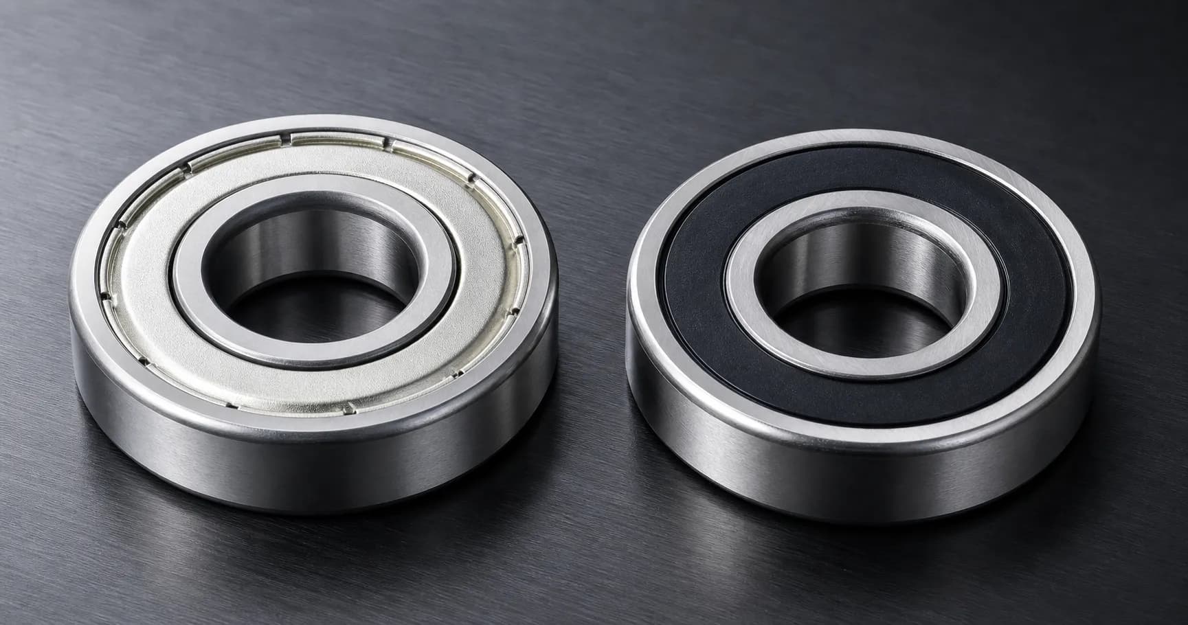
Every standard rolling bearing is defined by three boundary dimensions in millimeters: bore, outer diameter, and width. These three numbers are what the ISO 15 boundary-dimension standard codifies, and they are what every major manufacturer (SKF, NSK, Schaeffler/FAG, NTN, Timken) lists at the top of every catalogue page.
- Inner diameter (bore, d): the diameter of the hole that fits onto the shaft. This is the most important dimension because it sets the shaft fit.
- Outer diameter (D): the diameter of the bearing's outside surface, which fits inside the housing bore.
- Width (B): for radial bearings, the axial thickness of the bearing measured between the two side faces.
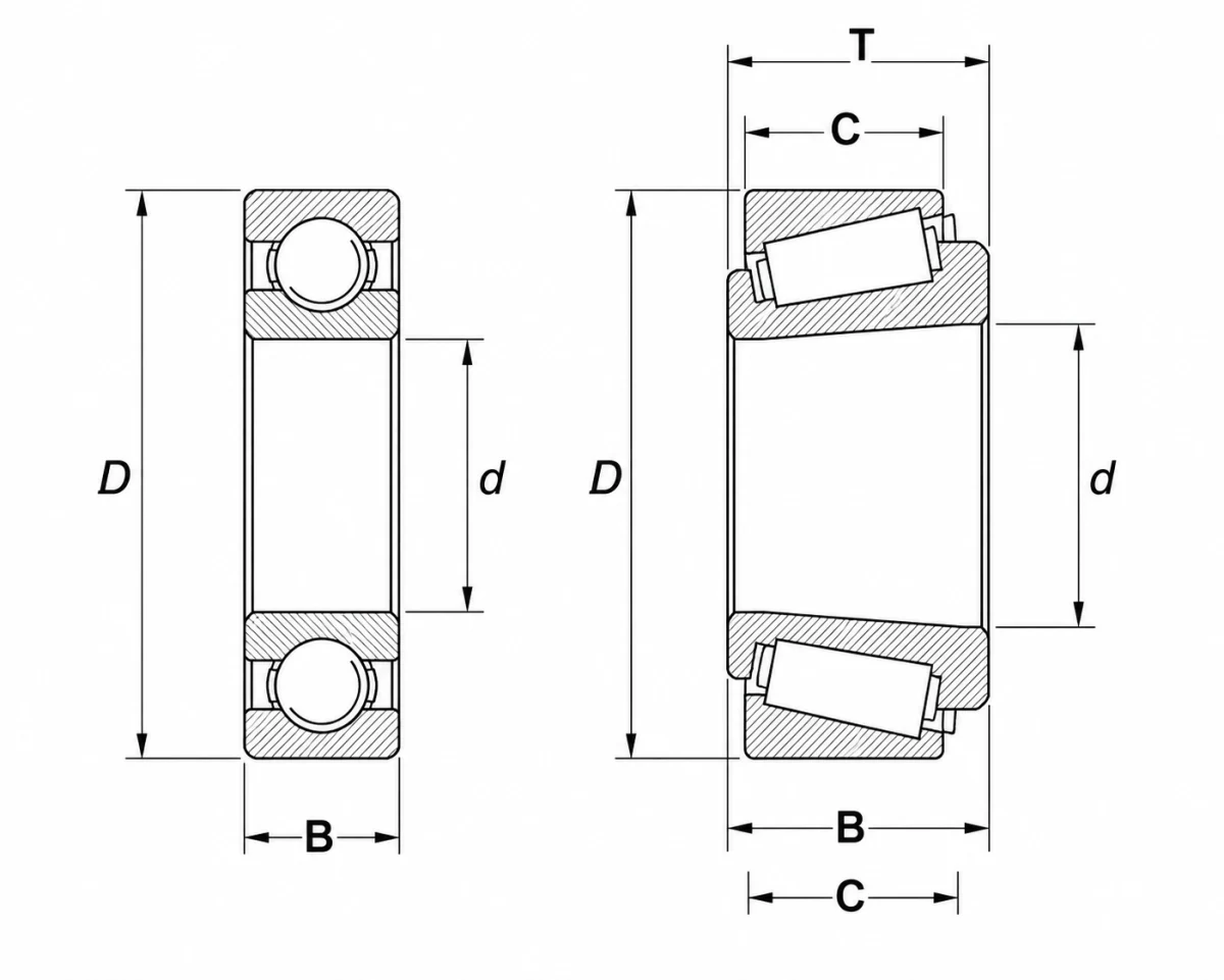
For tapered roller bearings, the geometry is different and the symbols change accordingly:
- T is the overall assembled width (cup + cone + roller stack).
- B is the width of the cone (inner ring) only.
- C is the width of the cup (outer ring) only.
This distinction matters because the cup and cone of a tapered roller bearing ship as separable components: measuring only the cone and reporting it as the bearing's width is one of the most common ordering mistakes. For background on why this geometry exists, see our guide on tapered vs. cylindrical roller bearings.
What Tools Do You Need to Measure a Bearing?
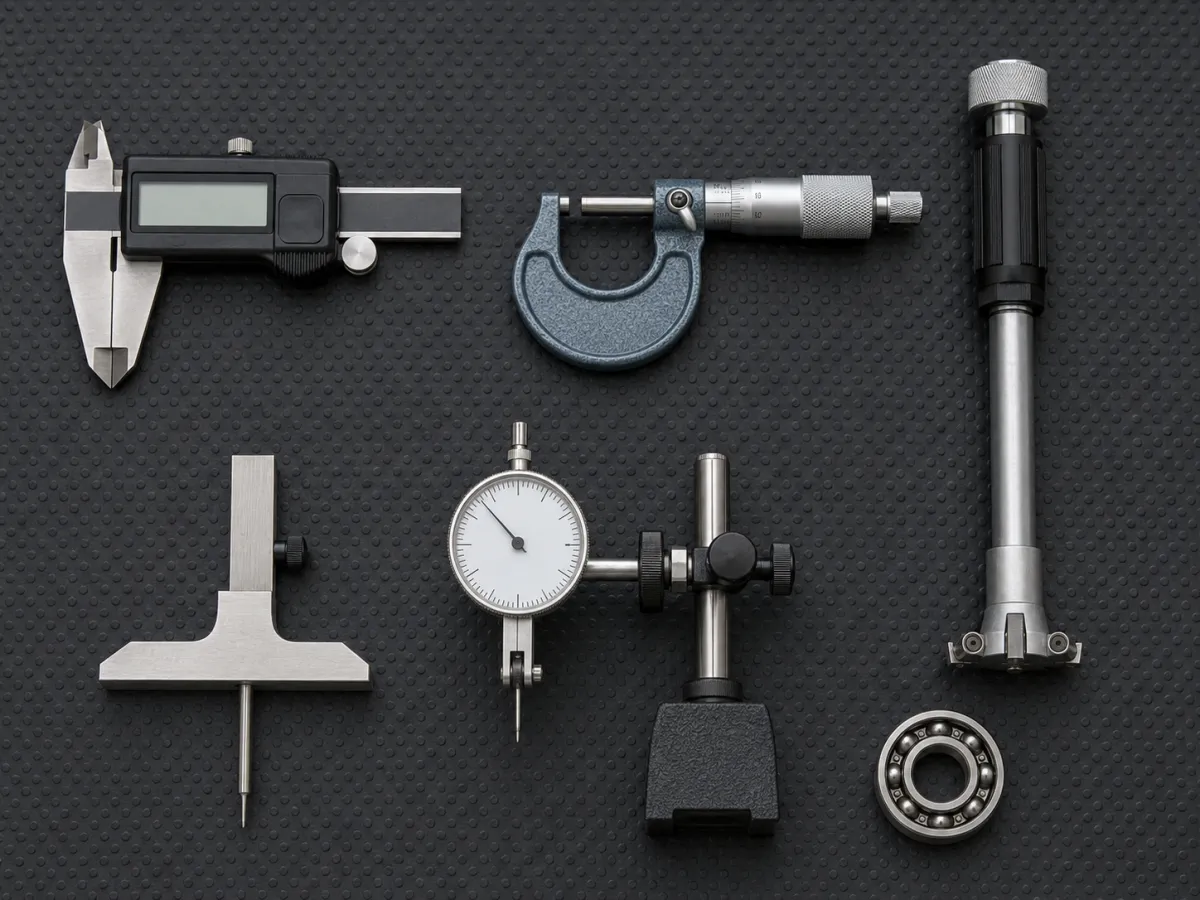
For most replacement and inspection work, three measuring tools cover roughly 95% of cases. The choice depends on how tight the tolerance is and how big the bearing is.
| Tool | When to use | Typical resolution |
|---|---|---|
| Digital caliper (0–150 mm) | Standard radial bearings up to ~140 mm OD | 0.01 mm |
| Digital caliper (0–300 mm) | Larger bearings, mounted units, pillow blocks | 0.01 mm |
| Outside / inside micrometer | Precision bearings (P5, P4, P2 per ISO 492) | 0.001 mm |
| Bore gauge or three-point internal micrometer | Inner-ring bores larger than 50 mm where caliper accuracy degrades | 0.001 mm |
| Depth gauge or caliper depth rod | Width B and tapered widths T, B, C | 0.01 mm |
A standard digital caliper is enough to identify the nominal size. If you are inspecting a precision spindle bearing or chasing a fit problem, the caliper will not be adequate: bore tolerance for an ISO 492 P0-class bearing is typically only +0/-8 μm to +0/-15 μm depending on size, well below caliper resolution.
Always measure at room temperature (20 °C / 68 °F), the reference temperature for ISO and ABMA bearing tolerances. Bearing steel expands by roughly 11–12 μm per meter per °C: the linear thermal expansion coefficient is ≈ 11.5 × 10⁻⁶ /°C for through-hardened bearing steel like AISI 52100 / GCr15 (AZoM). A 100 mm bore measured at 30 °C reads about 12 μm larger than the same bearing at 20 °C, enough to skew a precision check.
How to Measure a Bearing: Step-by-Step
The procedure below assumes you have removed the bearing from the machine, cleaned it of grease and dirt, and let it return to room temperature. If the bearing is still pressed onto a shaft, you can measure the OD and width but not the bore.
Step 1 — Clean the Bearing
Wipe off all grease and debris with a lint-free cloth. Particles trapped under the caliper jaws or between the bore and the gauge anvils introduce errors of 50 μm or more. For heavily contaminated bearings, use a degreaser or kerosene bath, then dry thoroughly. Never measure a bearing while it is hot from operation.
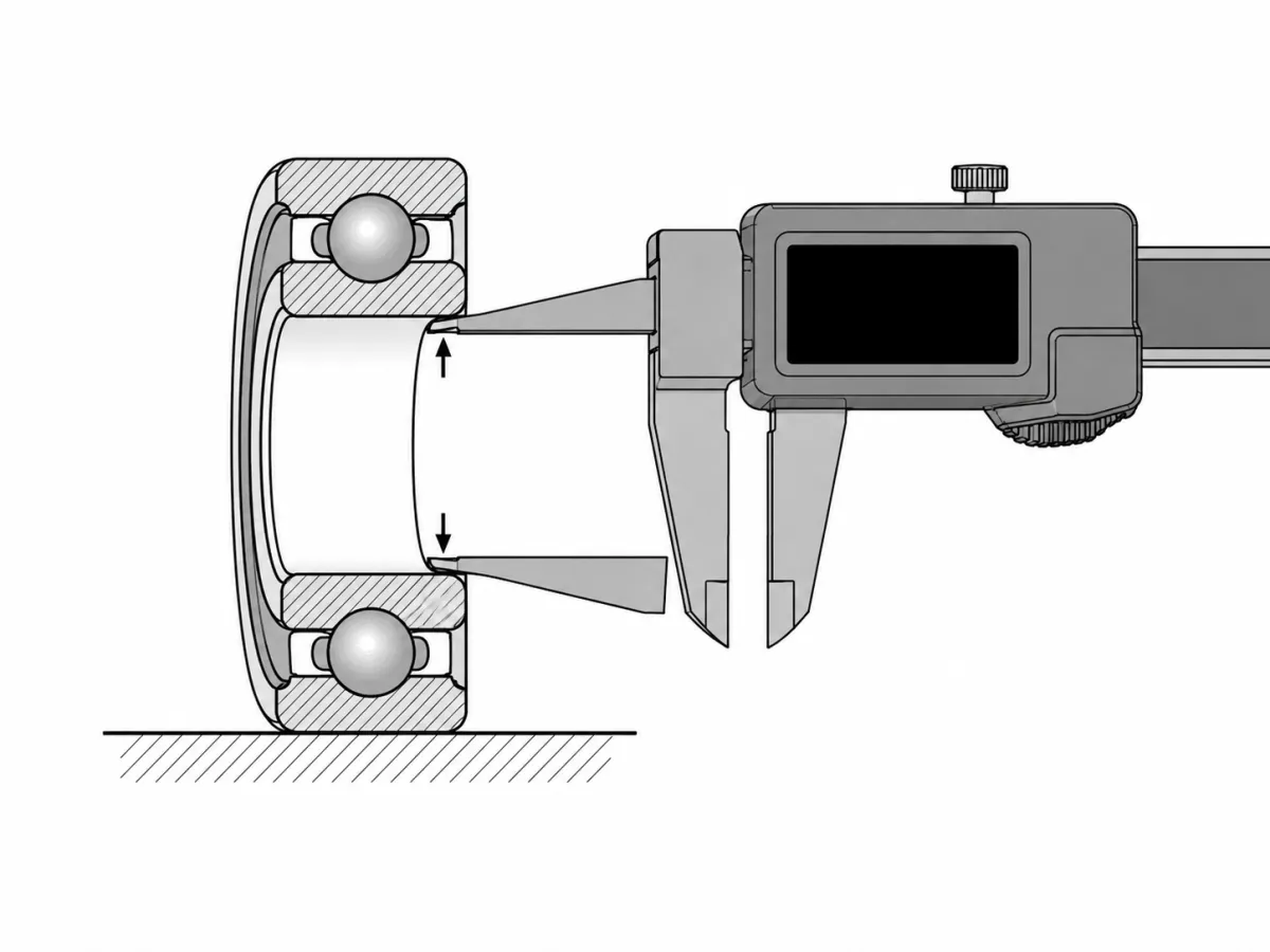
Step 2 — Measure the Bore (d)
Open the caliper jaws and slide the inside-measurement tips into the bore. Rock the caliper gently to find the maximum reading; this is the true diameter at that orientation. Take three measurements at roughly 120° intervals to catch any roundness deviation, and note both the maximum and minimum readings.
For a standard inner-ring bore, ISO 492 specifies an upper deviation of zero with a negative lower deviation. In other words, the bore may only be smaller than nominal, never larger. To check acceptance, the largest measured diameter must not exceed the nominal bore, and the smallest must not fall below the lower tolerance. For a quick check against the upper limit, record the largest of the three readings, not the smallest.
For bearings larger than about 50 mm bore, a digital caliper begins to lose accuracy due to jaw flex. Switch to an inside micrometer or a three-point bore gauge for anything larger or for any precision-class bearing.
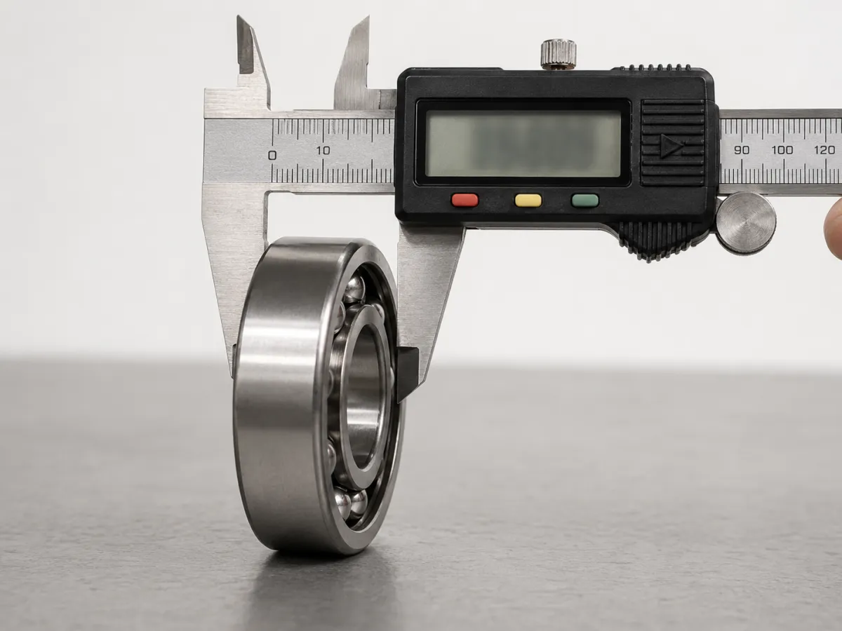
Step 3 — Measure the Outer Diameter (D)
Use the outside (jaw) measurement faces of the caliper. Again, take readings at three points 120° apart around the circumference and average them. The outer ring is usually the dimension easiest to measure accurately because it is fully accessible with no obstructions.
Step 4 — Measure the Width (B or T)
Stand the bearing on a flat surface and use the depth rod or measurement faces of the caliper across the two side faces. For a deep-groove ball bearing or cylindrical roller bearing, this gives you B directly.
For a tapered roller bearing, you have to decide which width you are measuring:
- If the cup and cone are still assembled with the rollers in place, you are measuring overall width T.
- If you are measuring the cone alone (separated), you are measuring B.
- If you are measuring the cup alone, you are measuring C.
Catalogue pages list all three for tapered bearings; for replacement purposes, T (or the boundary dimensions d × D × T) is the figure to match.
Step 5 — Cross-Check Against the Bearing Number
Before ordering a replacement, decode the bearing number printed on the outer ring (more on this in the next section). The last two digits of most metric bearing designations encode the bore size, so a quick lookup confirms whether your physical measurement is correct. If the printed number says the bore is 30 mm and your caliper says 29.7 mm, something is off. The bearing may be non-standard, badly worn, or your measurement is wrong — investigate before ordering.
How Do You Read Bearing Numbers to Find the Size?
Most metric rolling bearings encode their bore size directly in the last two digits of the bearing number, per the ISO 15 designation system. This is the fastest way to identify a bearing without any tools at all — provided the markings are still legible.
The rule for the bore-code (the last two digits of the basic designation):
| Bore code | Bore diameter (mm) |
|---|---|
| 00 | 10 |
| 01 | 12 |
| 02 | 15 |
| 03 | 17 |
| 04 and up | bore code × 5 |
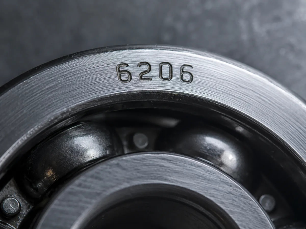
So a bearing marked 6204 has a bore of 20 mm (04 × 5). A bearing marked 6206 has a bore of 30 mm (06 × 5). A bearing marked 22220 is a spherical roller bearing with a bore of 100 mm (20 × 5).
Bore-code exceptions
The rule has exceptions:
- Bores below 10 mm are stated explicitly (e.g., 608 = 8 mm bore).
- Bores from 500 mm and up are written in full as a slash-suffix (e.g., 6/500 = 500 mm bore).
- Inch-series bearings (common in tapered roller bearings under the Timken designation system) use a completely different coding convention based on basic series numbers and do not follow the millimeter rule above.
The other digits of the designation tell you the bearing series and type. For example, in 6206:
- 6 = bearing type (deep groove ball bearing, single row).
- 2 = dimension series (related to width and outer diameter ratios per ISO 15).
- 06 = bore code → 30 mm bore.
This is why an experienced buyer can read a bearing number out loud and immediately know whether it is the right size, even before the bearing is in their hand. For more on the bearing types covered by these designations, see different kinds of bearings.
Common Mistakes When Measuring Bearings
These are the failure modes we see most often when buyers send us measurements for cross-reference. Each one has cost a real customer a re-order or a wrong-spec install.
What we see in our cross-reference inbox. Of the last roughly 200 customer measurement requests our technical team handled in early 2026, the chamfer-vs-cylindrical-surface mistake (item #6 below) accounted for the single largest cluster of "wrong measurement" emails: caliper jaws resting on the chamfer at the face of the outer ring, returning an OD that was 0.3 to 0.6 mm larger than the true value on bearings in the 50 to 120 mm OD range. Cone-vs-overall-width confusion on tapered bearings (item #2) was the next most common, almost always on automotive wheel-hub replacements where the original cone was still in the hub and only the cup had been shipped in for inspection.
1. Measuring a worn bearing as the nominal size. A bearing that has run for years can have a bore that has wear-grown by 50–200 μm. Always cross-check against the printed bearing number rather than treating the worn dimension as the original size.
2. Confusing B with T on tapered roller bearings. Reporting the cone width B as the bearing width T leads to ordering a replacement that is too narrow for the housing. Always measure the assembled bearing with cup and cone together for T, or look up T from the catalogue once the basic designation is known.
3. Measuring while warm. A bearing pulled from a machine running at 70 °C will read about 50 μm larger on a 100 mm dimension than the same bearing at room temperature. Wait for it to cool before measuring precision dimensions.
4. Using a worn or uncalibrated caliper. Verify the caliper zero against a gauge block or a known reference before precision work. A miscalibrated caliper can be off by 50 μm or more even when the digital readout looks confident.
5. Ignoring tolerance class. Two bearings with identical nominal dimensions can have very different tolerance classes per ISO 492: P0 (normal), P6, P5, P4, P2, in increasing order of precision. A high-speed spindle that needs P4 cannot be replaced with a P0 bearing of the same nominal size. The tolerance suffix appears in the full designation (e.g., 7008 CDGA/P4A is a P4-class angular contact bearing).
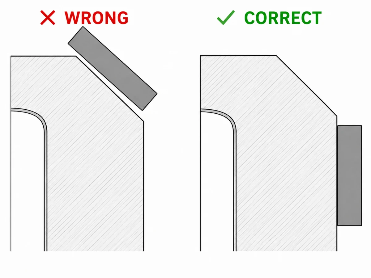
6. Measuring the chamfer instead of the bore or OD. Bearing rings have small chamfers (defined in ISO 582) at every edge. If the caliper jaw rests on the chamfer rather than on the cylindrical surface, the reading will be larger than the true bore (the chamfer flares outward at the face) or smaller than the true OD (the chamfer narrows the ring at the face), typically by 0.1 to 1 mm depending on the bearing size. Always seat the jaws against the cylindrical raceway-side surface, not the chamfered edge.
7. Measuring radial internal clearance with a caliper. Radial internal clearance (the freedom of the inner ring to move radially relative to the outer) is measured with feeler gauges or specialized clearance gauges, not calipers. Standard clearance values for various bearing types are defined in ISO 5753-1.
What If You Cannot Read the Bearing Number?
If the printed designation is worn off, corroded, or covered in paint, you must rely on physical measurement. Take all three boundary dimensions (d, D, B or T), measure the rolling-element type if visible (ball, cylindrical roller, tapered roller, spherical roller, needle), count the number of rows, and note any obvious features (sealed, shielded, snap-ring groove, flanged outer ring).
When ANDE's technical team works through this process for a customer, those inputs typically narrow the candidate list to a handful of designations — often just two or three. The application context narrows it further: if the bearing came out of a rolling mill, a paper machine, or a wind-turbine main shaft, it is almost certainly a spherical roller bearing, cylindrical roller bearing, or tapered roller bearing.
For very old or non-standard bearings (legacy Russian GOST designations, obsolete inch series, special OEM-coded units), the manufacturer's catalogue cross-reference is sometimes the only way to confirm the part. ANDE Bearing maintains cross-reference lookups for SKF, NSK, FAG, Timken and other major brand designations — if you have measurements but no readable number, it is usually faster to send the dimensions to a technical contact than to guess.
Bearing Tolerance Classes at a Glance
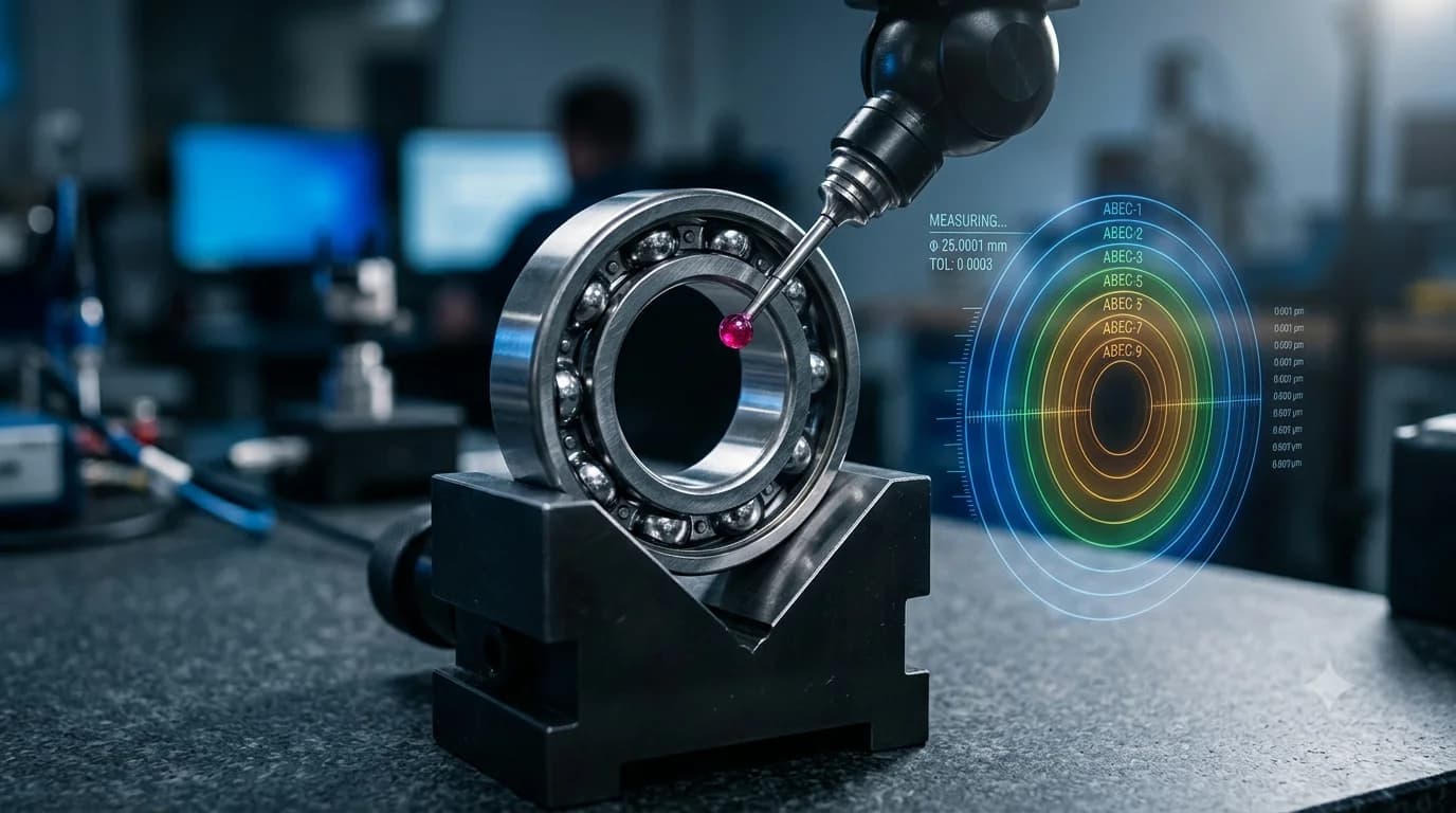
For replacement work, the nominal dimension is only half the story; the tolerance class controls how tightly the bearing fits the shaft and housing. The bore-tolerance band shrinks roughly fourfold from P0 to P2, and the table and chart below summarize the ISO 492 classes alongside their ABEC equivalents (NSK tolerance tables).

| ISO 492 class | Equivalent ABMA class | Typical application |
|---|---|---|
| Normal (P0) | ABEC 1 | General industrial, gearboxes, electric motors |
| P6 | ABEC 3 | Precision gearboxes, machine-tool feeds |
| P5 | ABEC 5 | Machine-tool spindles, instrument bearings |
| P4 | ABEC 7 | High-speed spindles, precision pumps |
| P2 | ABEC 9 | Ultra-high-precision spindles, gyroscopes |
A higher precision class means tighter tolerances on bore, OD, width, runout, and raceway form. The cost rises substantially with each step up: a P4 spindle bearing typically costs 3 to 10 times the equivalent P0 bearing.
FAQ
Q: How do you measure bearings without removing them from the shaft?
You can measure the outer diameter and overall width with a caliper while the bearing is still installed, but you cannot directly measure the bore. The most reliable workaround is to read the bearing number printed on the outer ring and decode the bore from the last two digits per ISO 15. If the marking is illegible, you may need to remove the bearing or use a borescope to read any markings on the inner ring.
Q: How do you measure a tapered roller bearing?
Measure the bore d of the cone (inner ring), the outer diameter D of the cup (outer ring), and the overall assembled width T with cup and cone seated together as in operation. Catalogue listings always provide T, B (cone width), and C (cup width) separately because the components are separable. The dimension to match for ordering is normally T together with d and D.
Q: What units are bearing dimensions measured in?
Standard ISO and DIN bearings are dimensioned in millimeters. Inch-series bearings — most commonly Timken-designation tapered roller bearings used in North American automotive and heavy-equipment applications — are dimensioned in inches. Always confirm the unit system before ordering, especially for bearings sourced for vehicles or equipment originally engineered in inch units.
Q: How accurate does my measurement need to be?
For identifying a standard P0-class bearing for replacement, ±0.1 mm is usually enough — the dimension steps in the ISO 15 catalogue are large enough that a 0.1 mm error rarely lands you on the wrong bearing. For inspection of a precision spindle bearing or for checking shaft and housing fits, you need micrometer-grade accuracy (±1 μm) and a controlled-temperature environment.
Q: Can I measure a bearing's load capacity or service life?
No, those are calculated, not measured. Dynamic and static load ratings (C and C₀) are derived from bearing geometry and material properties per ISO 76 (static) and ISO 281 (dynamic). Service life is calculated from the L₁₀ formula: L₁₀ = (C/P)ᵖ million revolutions, where p = 3 for ball bearings and p = 10/3 for roller bearings. The catalogue value of C is the figure you use; you cannot determine it from a caliper measurement.
Conclusion
Measuring a bearing is a five-minute job once you know the three dimensions — bore, outer diameter, and width — and which tool fits the job. For routine replacement, a digital caliper and the bearing number printed on the outer ring are usually all you need; the ISO 15 bore-code rule (last two digits × 5 for bore codes 04 and up) lets you cross-check the measurement in seconds.
The trap is precision work, where caliper accuracy is not enough and tolerance class quietly determines whether the new bearing will fit. Whenever the application is a high-speed spindle, a precision feed mechanism, or any bearing carrying a P-class suffix in its designation, switch to a micrometer, work at room temperature, and verify the tolerance class before ordering.
If you are sizing a replacement and want a second pair of eyes on your measurements before you order, ANDE Bearing's technical team handles cross-reference identification and dimension verification daily — feel free to send your measurements and any photos of the markings for confirmation.
About the Author
Jeff Li writes on bearing engineering and applications for ANDE Bearing. Connect on LinkedIn.