An angular contact bearing looks almost like an ordinary ball bearing, but it does something a deep-groove bearing can't: it carries a heavy push along the shaft at the same time it carries the load across it. That's why a CNC spindle can hold micron accuracy at 15,000 rpm and a car wheel can survive hard cornering. The whole trick comes down to one number — the contact angle — and one habit that trips up almost everyone the first time: these bearings are almost always sold and mounted in pairs.
Why pairs? Because a single row only takes thrust in one direction. Turn it around and it can't hold the shaft at all. This guide walks through what the contact angle actually does, the standard angles and what they trade off, single versus double row, the DB/DF/DT duplex arrangements, preload, and the two comparisons engineers ask most — angular contact versus deep-groove and other ball bearings, and angular contact versus tapered roller.
Key Takeaways
- An angular contact ball bearing transmits load along a line set at a contact angle (typically 15°, 25°, 30° or 40°), letting it carry combined radial and axial load — but axial load in one direction only (NTN Global catalog).
- Because a single row takes thrust one way, angular contact bearings are almost always mounted in matched pairs — DB (back-to-back, high moment stiffness), DF (face-to-face, tolerates misalignment) or DT (tandem, shares heavy one-way thrust).
- A larger contact angle raises axial capacity and lowers radial capacity; smaller angles favor radial load and higher speed.
- Preload trades stiffness and running accuracy against heat and fatigue life — the core spindle-design decision.
- The contact-angle letter codes (A/B/C/E) vary by manufacturer — always check the maker's catalog before you order.
What Is an Angular Contact Ball Bearing?
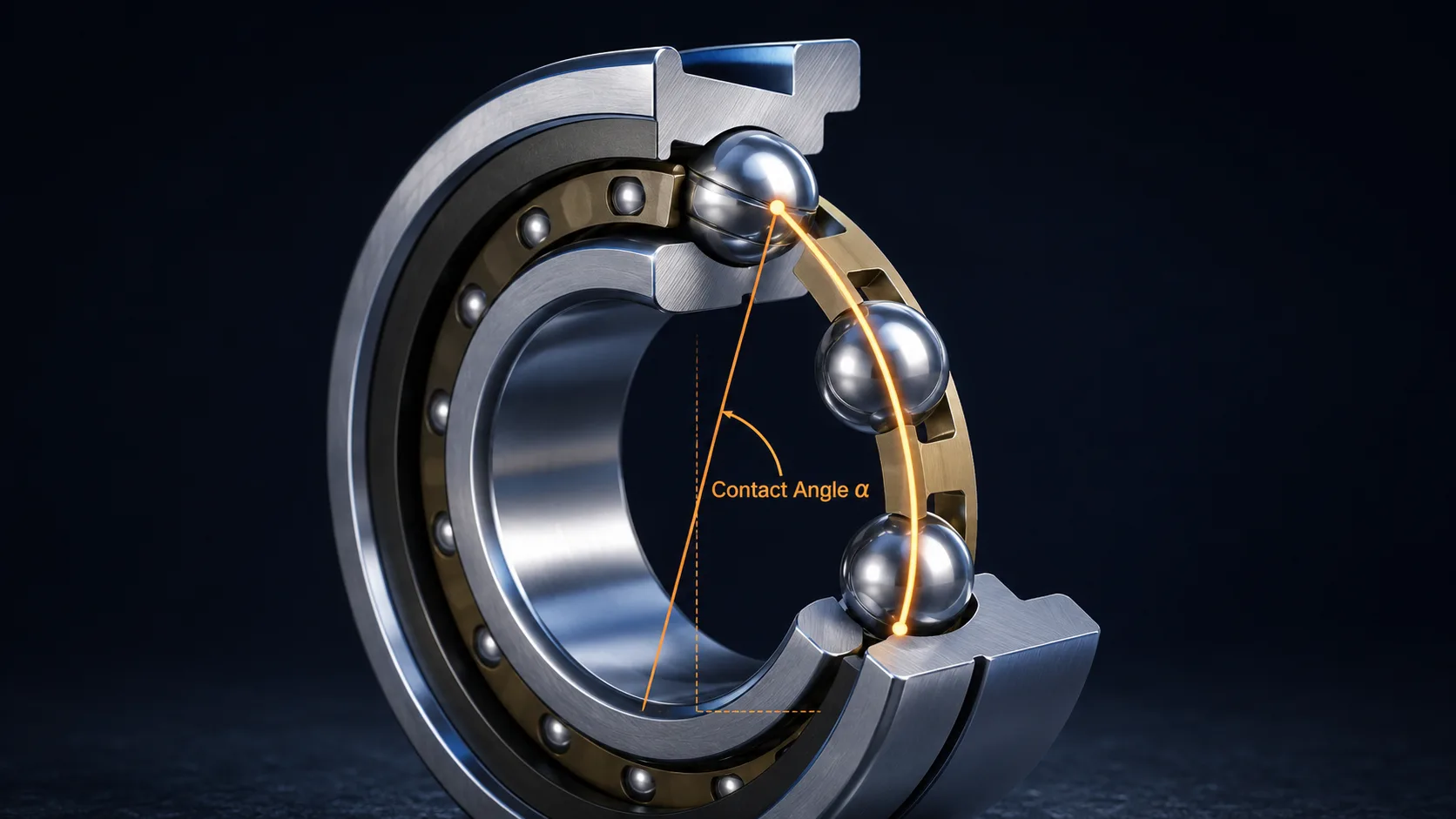
An angular contact ball bearing is a ball bearing whose inner and outer raceways are offset so that load transfers along a line set at a defined contact angle to the radial plane — letting one bearing carry combined radial and axial load, though axial load in a single direction only (NTN Global catalog). Change that angle and you change the whole character of the bearing.
Picture a normal deep-groove bearing: the balls sit at the bottom of a symmetric groove, and load pushes straight through the center, perpendicular to the shaft. Now imagine tilting the raceway shoulders so the balls contact them slightly off-center. The load no longer runs straight across — it runs at an angle, part of it pushing radially and part of it pushing along the shaft. That angled load line is the entire idea.
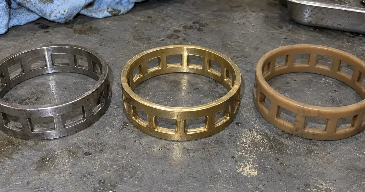
The parts are familiar: an inner ring, an outer ring, a set of balls, and a cage. What differs is the geometry. One shoulder on each ring is cut higher than the other, so the ball rests against a high shoulder on one side and a low (or relieved) shoulder on the other. This is why the bearing takes thrust one way but not the other — push the shaft the wrong direction and the balls simply ride up over the low shoulder.
That one-directional limit is the reason these bearings live in pairs. A single row handles thrust in one direction; its partner, mounted facing the opposite way, handles the other. ANDE builds its angular contact ball bearing range as both single-row units for duplexing and pre-set double-row units. If you're still choosing among bearing families, our guide to different kinds of bearings puts angular contact in context first.
Contact Angle Explained: 15°, 25°, 30° & 40°
The contact angle sets the split between radial and axial capacity: a larger angle carries more thrust and less radial load, a smaller angle carries more radial load and runs faster and cooler. Contact angles typically fall between 10° and 45°, and the standard nominal values are 15°, 25°, 30° and 40° (NTN Global catalog). Think of it as a dial you set at design time.
Here's the intuition. At a shallow 15°, the load line is nearly across the shaft, so the bearing behaves close to a stiff deep-groove bearing — good radial capacity, high speed, modest thrust. Crank the angle up to 40° and the load line tilts toward the shaft axis, so axial capacity climbs sharply while radial capacity and speed drop. Most machine-tool spindles pick 15° or 25° for speed; wheel hubs and screw-drive supports lean toward the larger angles for thrust.
The catch is the naming. The contact angle is encoded as a letter in the part number, but the letters are not universal across manufacturers. NTN's catalog states plainly that a bearing coded "B" has a 40° contact angle, while one with no such code sits at 30°; their "C" denotes 15°, and code "A" is omitted from the part number entirely (NTN Global catalog). SKF, NSK and FAG each define these letters slightly differently. So the rule is simple: read the angle from the maker's own catalog, never from a letter you assume you recognize.
Single-Row vs Double-Row Angular Contact Bearings
A single-row angular contact bearing takes thrust in one direction and needs a partner to handle the other; a double-row unit packs two angular-contact rows into one ring set, so it takes thrust both ways in a single mounting. The choice comes down to whether you want to build and preload a set yourself, or buy a self-contained unit with the geometry already fixed at the factory.
Single-row bearings are the building block of precision spindles. You buy them individually (or as matched sets) and arrange them to suit the load and stiffness you need — which is exactly what the DB/DF/DT section below is about. They give the designer control over preload and arrangement, at the cost of having to get that arrangement right.
Double-row angular contact bearings solve the problem in one part. Two rows of balls run at opposing contact angles inside a common outer ring, so the unit resists thrust in both directions and handles tilting moments without a second bearing. This is the classic automotive wheel-hub geometry — compact, pre-set, and able to shrug off the reversing side loads of cornering. Our automobile ball bearings guide covers those hub units in more depth, and the different kinds of bearings overview shows where each sits.
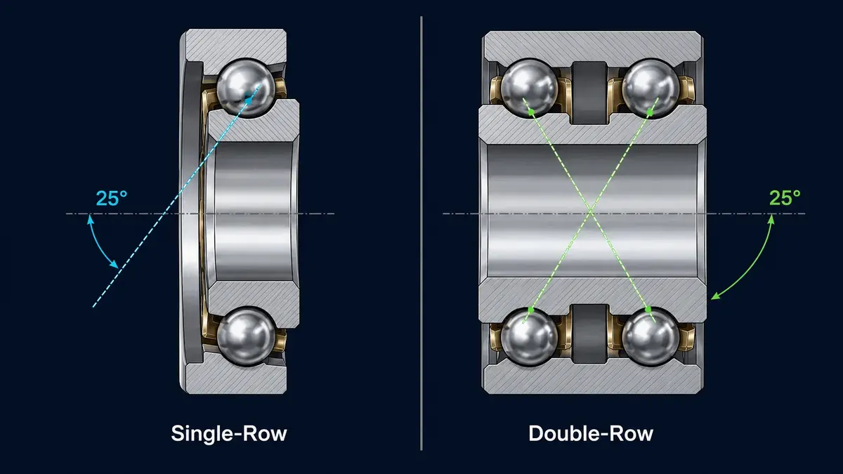
When do you pick which? Use double-row when you want moment stiffness and bidirectional thrust from a single compact part and don't need to tune preload — wheel hubs, pumps, gearbox output shafts. Use single-row when you're designing a precision spindle and want to choose the arrangement, contact angle, and preload class deliberately. The rest of this guide focuses on single-row, because that's where the design decisions live.
DB, DF & DT: Duplex Arrangements Decoded
Matched single-row bearings are arranged three ways — DB (back-to-back), DF (face-to-face) and DT (tandem) — and each has a distinct load, stiffness and misalignment profile. Get this choice wrong and a spindle either whips under moment load or seizes from over-constraint. The NTN catalog is the authoritative reference for how each behaves (NTN Global catalog).
DB (back-to-back), sometimes drawn as an "O". The two outer-ring backs face each other, so the load lines diverge outward. This gives a wide effective load-center spacing and high moment (tilting) stiffness, but only a small allowable misalignment. DB is the default for machine-tool spindles, where resisting the bending moment of an overhung cutter matters most. It carries thrust in both directions.
DF (face-to-face), drawn as an "X". The outer-ring faces meet, so the load lines converge inward. Load-center spacing is narrow, moment stiffness is lower, but the arrangement tolerates more shaft misalignment and mounting error. DF suits assemblies where alignment is imperfect or where the housing and shaft may deflect differently. It also carries thrust both directions.
DT (tandem). Both bearings face the same way, so they share a heavy axial load acting in one direction — the thrust capacity roughly doubles, but the set does nothing for the opposite direction and must be paired with another bearing to locate the shaft. Use DT when one-way thrust is large, such as a vertical pump or a screw-drive support.
Where axial space is scarce, there is a fourth option worth knowing. A four-point contact bearing uses Gothic-arch raceways to carry radial, thrust and moment load in a single row of balls, doing in one bearing what a DB pair does in two. It is a staple of thin section bearings, where it is designated type X, and it is the geometry the most common slewing bearing scales up to a metre or more of diameter.
| Arrangement | Axial direction | Moment stiffness | Misalignment tolerance | Typical use |
|---|---|---|---|---|
| DB (back-to-back, "O") | Both | High | Small | Machine-tool spindles |
| DF (face-to-face, "X") | Both | Lower | Larger | Misalignment-prone mounts |
| DT (tandem) | One only | — (needs a partner) | — | Heavy one-way thrust (pumps, screw drives) |
Preload: Why It Makes or Breaks a Spindle
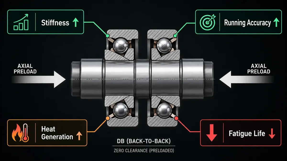
Preload is a built-in axial force pushing paired bearings against each other, removing internal clearance to raise stiffness and running accuracy — at the cost of more heat and shorter fatigue life. It's the single most consequential decision in a spindle design, and the most common way to kill a bearing set prematurely. Too little and the spindle flexes; too much and it cooks.
Where does preload come from? Three ways. A universally matched set is ground so that clamping the rings flat against each other creates a precise, repeatable preload — you just bolt it up. Shims or spacers of a chosen thickness set the preload between the rings. Springs apply a constant light preload that stays roughly steady as the shaft grows with heat. Light, medium and heavy preload classes trade the same axis every time: heavier preload means more stiffness and running accuracy, but more friction heat and less fatigue life.
From our shop floor: The two mistakes we see most on returned duplex sets are mixing bearings from different matched sets and installing a set backwards. Matched sets carry orientation marks (a line or "V" across the outer rings) for a reason — the grinding is matched as a set, so a bearing from another set won't give the rated preload. And DB versus DF is not interchangeable: reverse the pair and you swap high moment stiffness for misalignment tolerance without meaning to. Preserve the fit too — an over-tight shaft fit adds unintended preload on top of the designed value and pushes the set toward the heat-and-fail end of the curve.
Preload also interacts with internal clearance. Standard radial clearance groups run C2, CN (normal), C3 and C4 per ISO 5753-1 (ISO 5753-1:2009); on an angular contact set, the mounted clearance and the preload are two sides of the same adjustment. Get the fatigue-life picture right by working the load through the dynamic vs static load ratings (C and C₀) before you commit to a preload class.
The payoff for getting it right is real. NSK reports its super-precision angular contact bearings deliver roughly 15% longer fatigue life from higher-purity steel, and that sealed versions extend grease life by up to 50%, in contact angles of 15°, 25° and 30° (NSK Americas). Treat those as NSK's own performance claims for its premium line, not an independent benchmark — but they show how much the details of steel, seal and preload matter at the top of the range.
Angular Contact vs Deep Groove vs Tapered Roller
Choose by load pattern and speed: deep groove for mostly-radial general duty, angular contact for combined load at high speed and precision, tapered roller for heavy combined load at lower speed. All three can carry radial and axial load together, but their sweet spots barely overlap — which is why "just use a deep groove" or "just use a tapered roller" so often lands wrong.
Angular contact vs deep groove. A deep-groove bearing is cheaper, simpler, and takes modest thrust in both directions from one bearing. An angular contact bearing takes far more thrust, offers higher axial stiffness, and runs true at higher speed — but only one direction per row, so you pay for a pair. If your load is mostly radial with light incidental thrust, deep groove wins on cost and simplicity. Once thrust becomes significant, or you need spindle-grade stiffness and precision, angular contact is the right tool.
Angular contact vs tapered roller. This is the comparison most guides skip. A tapered roller bearing replaces the ball with a rolling cone, trading point contact for line contact — so it carries much heavier combined loads for its size. But line contact means more friction, more heat and lower speed. An angular contact ball bearing wins decisively on speed, precision and low running torque; a tapered roller wins on raw combined-load capacity at moderate speed. Our tapered vs cylindrical roller bearings guide covers the roller side in detail. For loads that are purely axial, neither is ideal — a thrust bearing is the right architecture.
How to Mount Angular Contact Bearings & Read the Designation
Correct mounting means installing the matched set in its intended orientation, preserving preload through the right fits, and never mixing bearings across sets. Most premature failures in duplex sets trace back to one of those three, not to the bearing itself. A repeatable procedure prevents the majority of them.
The sequence: confirm the arrangement (DB or DF) and align the orientation marks so the set faces the way the design intends; clean the shaft and housing and check them for burrs; select fits that hold the rings without adding unintended preload (a common trap — an over-tight interference fit on the inner ring squeezes the set tighter than designed); mount squarely without hammering on the outer ring to seat the inner; then lubricate to the specified fill and set the locknut to spec. For dimensional checks before mounting, our how to measure a bearing guide covers bore, OD and width against ISO 15 boundary dimensions.
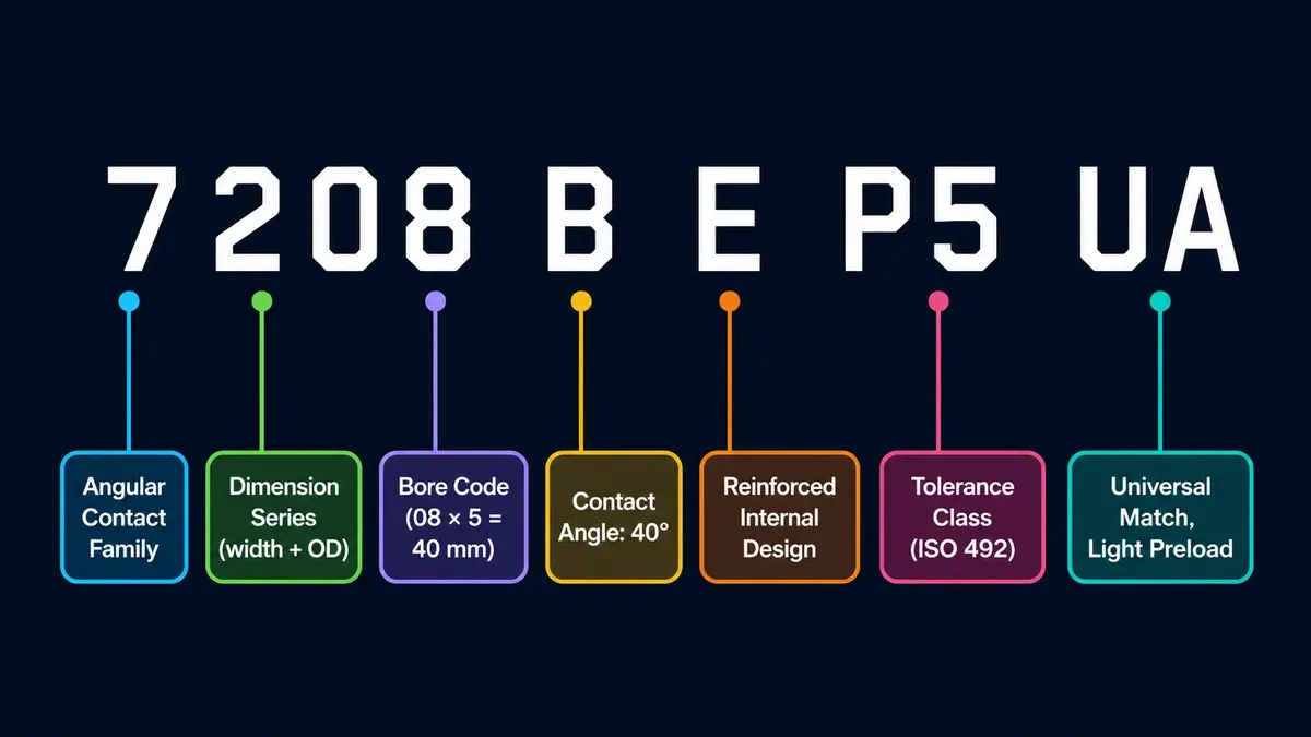
Reading the part number is the other half. Take 7208 B E P5 UA as a worked example. The leading 7 marks the angular contact family; 2 is the dimension series; 08 is the bore code (08 × 5 = 40 mm bore). B is the contact-angle code (40° in NTN's system — but confirm per maker). E flags a reinforced or high-capacity internal design. P5 is the ISO tolerance class, and UA denotes a universally matchable bearing for light preload when duplexed. Decode left to right and every SKU tells you its geometry.
Precision class is where angular contact ties back to speed. Tolerance classes run Normal, 6, 5, 4 and 2 in increasing precision per ISO 492 (ISO 492:2023), which catalogues print as the DIN 620 codes P0, P6, P5, P4 and P2; high-speed spindles typically demand P4 or P2, where a P0/Normal bearing of the same nominal size would run rough and hot. This is the same precision ladder behind the ABEC bearing rating system — ABEC classes map onto these ISO/P classes.
Standards, Load Ratings & Where Angular Contact Bearings Are Used
Angular contact bearings are governed by the same rolling-bearing standards as the rest of the family: ISO 15 for boundary dimensions, ISO 281 for dynamic load rating and life, ISO 76 for static rating, ISO 492 for tolerances, and ISO 5753-1 for internal clearance — with ABMA Standards 9 and 20 as the US counterparts. That shared framework is why a 7208 from one maker interchanges dimensionally with another's.
Life follows the ISO 281 rating-life formula, L₁₀ = (C/P)ᵖ, with p = 3 for ball bearings, where C is the dynamic load rating and P the equivalent load (ISO 281:2007). For an angular contact set, P must account for the induced axial load that the contact angle generates under radial load — a detail the catalog's load factors handle, and a reason the arrangement and angle feed directly into calculated life. On converting Fr and Fa into one equivalent load, including why the induced component belongs in the load case even when nothing external pushes on the shaft, see the guide to axial versus radial load.
Where do they earn their keep? Anywhere combined load meets speed or precision: machine-tool spindles (the classic DB application), high-speed pumps, gearboxes, automotive wheel hubs and EV traction motors, robotics joints, and aerospace accessories. In rolling mills, angular contact ball bearings appear specifically where high precision and high speed are required — see our roll mill bearings breakdown. At the extreme, angular-contact spindle bearings carry the highest speed ratings of any ball bearing type. Take the nDm limit from the manufacturer's catalog for the specific series, arrangement, preload, and lubrication method — never from a single class-wide figure.
For market context: angular contact bearings are a segment of the broader ball-bearing market, which Market Research Future put at roughly US$20.82 billion in 2024, projected to US$31.69 billion by 2035 at a 3.89% CAGR, with deep-groove the single largest type (Market Research Future). No reputable publisher isolates an angular-contact-specific figure, and ball-bearing market totals diverge widely between research firms — so read any single number as one firm's estimate, not settled fact.
Frequently Asked Questions
Q: What is an angular contact ball bearing used for?
Angular contact ball bearings handle combined radial and axial load at high speed or precision. Typical uses are machine-tool spindles, high-speed pumps, gearboxes, automotive wheel hubs, robotics joints and aerospace accessories. They carry axial load in one direction per row, so they're almost always mounted in matched pairs. Contact angles run from about 10° to 45° (NTN Global catalog).
Q: What do the contact angles 15°, 25°, 30° and 40° mean?
The contact angle sets the balance between radial and axial capacity. A smaller angle (15°) favors radial load and higher speed; a larger angle (40°) favors axial load. Standard nominal angles are 15°, 25°, 30° and 40°. The letter code for the angle (A, B, C, E) varies by manufacturer — NTN's "B" is 40° — so always confirm against the maker's catalog (NTN Global catalog).
Q: What is the difference between DB, DF and DT arrangements?
DB (back-to-back, "O") gives high moment stiffness and wide load-center spacing but small misalignment tolerance — the spindle default. DF (face-to-face, "X") has lower moment stiffness but tolerates more misalignment. DT (tandem) faces both bearings the same way to share a heavy one-way thrust, and must be paired with another bearing to locate the shaft (NTN Global catalog).
Q: Why are angular contact bearings mounted in pairs?
A single row of an angular contact bearing carries axial load in only one direction — push the shaft the other way and the balls ride over the low raceway shoulder. Mounting a second bearing facing the opposite direction lets the pair carry thrust both ways and sets a controlled preload. That's why they're sold as matched, universally matchable, or double-row units.
Q: Angular contact vs tapered roller — which is better?
Neither is universally better; they fit different jobs. Angular contact ball bearings win on speed, precision and low running torque, so they suit spindles and high-speed shafts. Tapered roller bearings use line contact to carry much heavier combined loads at lower speed, so they suit heavy axles and gearboxes. Choose by load magnitude and speed — see our tapered vs cylindrical roller guide.
Conclusion
Angular contact bearings reward engineers who respect one idea: the contact angle sets everything. It decides how much thrust the bearing takes, which direction, how fast it can spin, and how stiff the shaft will be.
- Contact angle sets the radial-versus-axial split — 15° for speed and radial load, 40° for thrust.
- Pairs are the norm because one row takes thrust one way; DB, DF and DT pick your stiffness-versus-misalignment trade-off.
- Preload is the spindle lever — more stiffness and accuracy, but more heat and less life. Don't over-preload.
- Choose against deep groove and tapered roller by load ratio and speed, not habit.
- Read the designation and check the maker's catalog — the contact-angle letter codes aren't universal.
If you're specifying a matched set or a preload class for a spindle or high-speed shaft, browse ANDE's angular contact ball bearing range or contact our engineering team — we'll help you match contact angle, arrangement and preload to your application.