A maintenance planner can end up holding three documents that describe one bearing position. The chock drawing calls for 319254/VJ202. The quote that came back reads FCD500700500. A legacy stores record for the same stand says FC 100140500. Two of those three can be decoded with arithmetic. The third cannot be decoded at all, and none of them settles whether the bearing will actually fit and survive.
That is the specific problem with four-row cylindrical roller bearings. This is the one common bearing type whose part number is frequently not a designation in the sense the rest of a bearing catalogue uses the word. This guide covers how each numbering system works, what to specify once the envelope is fixed, and the mounting practice that decides whether the bearing reaches its rated life.
Key Takeaways
- These bearings take radial load and nothing else. SKF's equivalent load equations for the type are
P = FrandP₀ = Fr, with no axial term in either (SKF). The arrangement needs a separate thrust bearing.- Their boundary dimensions are not standardized. SKF gives dimension standards for the type as "Not standardized", qualified only by bore and outside diameter for many bearings following diameter series 9 or 0 of ISO 15 (SKF). Width is where the interchange risk lives.
- One bearing circulates under three incompatible numbering systems. SKF commonly uses an opaque drawing number, catalogue tables use a five-times-coded short form (
FC 2942155), and the long form spells the millimetres out (FCD145210155). All three can describe one 145 × 210 × 155 bearing.- Specify C3 or C4 clearance and confirm the tolerance class. Those are SKF's standard clearance executions per ISO 5753-1, with C2 reserved for the helical-groove variant.
- This bearing is designed to be rotated in service. Only about a quarter of the outer ring carries load under a constant load direction. The ring faces are therefore marked in four zones, and SKF recommends turning them 90° and inspecting after roughly 1,000 operating hours.
What a Four-Row Cylindrical Roller Bearing Is For
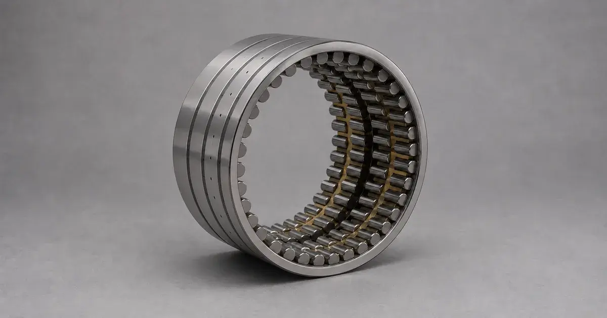
It is a radial-load-only bearing that packs the highest available radial capacity into a low cross-sectional height, which is why it dominates roll-neck positions in strip, plate, and long-product mills. Four rows of rollers distribute a very large radial load across a cross-section that a single-row design could not carry.
The reason the geometry wins is a machine-design consequence rather than a bearing-catalogue talking point. A low cross-sectional height allows a relatively large roll neck diameter compared with the roll diameter (SKF). A thicker bearing section would force either a smaller neck, which is weaker in bending, or a larger roll, which changes the whole mill. American Roller Bearing frames the same trade from the load side: the four rows carry large radial loads for the given bearing cross-section (American Roller Bearing).
Its axial ceiling is absolute, and worth stating without hedging. SKF's equivalent load equations for this type are P = Fr for dynamic load and P₀ = Fr for static load (SKF). There is no axial term in either equation, so any thrust in the position needs its own bearing. If you are still fixing the load path, the radial-only load path and the thrust bearing options are covered separately.
Axial displacement is a different matter, and it is an upside. Designs with no flange, or with one integral flange on either ring, accommodate axial displacement within defined limits with virtually no increase in friction. That behaviour is why the type serves as the non-locating bearing in a mill stand, absorbing thermal growth of the roll without loading itself axially. For the architecture-level choice against the tapered alternative, see four-row tapered against four-row cylindrical, and for selection across mill positions, the roll neck bearing selection guide.
Why the Part Number Is Not a Designation
For this bearing type the basic designation is usually a drawing number. SKF states outright that the drawing number itself does not provide any information about the bearing design or features (SKF). 319254/VJ202 is not decodable by any rule. It is an index into a catalogue, and without the catalogue it tells you nothing.
Part of the SKF system is systematic, and that part is worth knowing:
| Element | Meaning |
|---|---|
Prefix L | A separate inner or outer ring |
Prefix R | A ring with its roller-and-cage assembly |
BC4… | Four-row bearing |
BC2B… | Two matched double-row bearings |
NNUD | Four-row built from two NNU double-row designs |
Suffix K | Tapered bore, 1:12 |
Suffix K30 | Tapered bore, 1:30 |
Suffix F | Machined steel cage, roller-centred |
Suffix FA | Machined steel cage, outer-ring-centred |
Suffix M | Machined brass cage, roller-centred |
Source: SKF designation system and designs and variants (SKF).
Two other notations are decodable, and both are in daily circulation. The short catalogue form multiplies the first two digit groups by five to get bore and outside diameter, then reads the remaining group as width. The long form simply spells the millimetres out.
| Notation | Arithmetic | Result (d × D × B) |
|---|---|---|
FC 182870 | 18 × 5 = 90, 28 × 5 = 140, B = 70 | 90 × 140 × 70 |
FC 2942155 | 29 × 5 = 145, 42 × 5 = 210, B = 155 | 145 × 210 × 155 |
FCD145210155 | literal millimetres | 145 × 210 × 155 |
FCD 6084300 | 60 × 5 = 300, 84 × 5 = 420, B = 300 | 300 × 420 × 300 |
FCDP 114163594 | 114 × 5 = 570, 163 × 5 = 815, B = 594 | 570 × 815 × 594 |
Treat the short-form rule as market convention rather than as a standard, because no standard defines it. It earns its place here for one reason. It reproduces bore, outside diameter, and width exactly on every published distributor dimension row checked for this guide, including awkward widths like the 594 mm in the last row. Use it to identify an envelope. Never use a distributor table as the source of a load rating.
Now the part that costs money. Rows two and three of that table are the same 145 × 210 × 155 envelope written two ways, and the load ratings published against that envelope do not agree between sources. Distributor listings for the short form quote dynamic and static ratings that differ from ANDE's published figures for the long form, in both directions, and both notations trace back to the same SKF drawing number, BC4-0101. So the notation fixes the envelope and settles nothing about the internal design, the cage, or the basis on which a rating was calculated. Ask for the rating and its basis in writing. The envelope matching is the beginning of the comparison, not the end of it.
One conflation to guard against explicitly. The last-two-digits × 5 rule for standard bearing designations is a bore code, a different rule that only resembles this one. In a standard designation the coded digits are the last two before any suffix, and they encode bore alone. Here the multiply-by-five arithmetic runs across two separate digit groups and encodes bore and outside diameter, with width appended raw. If you are used to the bore-code rule for standard bearing designations, read this notation as a separate system and not as an extension of that one.
There is one more reason a part number may not describe what you think. Distributors commonly supply these bearings as outer-race roller assemblies and inner-race sets rather than as one unit (American Roller Bearing). A number on a purchase order may therefore describe half a bearing. That is a sensible way to stock roll-neck spares. It is a poor way to receive a quote you have not read closely.
FC, FCD, and FCDP: What the Prefix Changes
The three prefixes describe ring count and cage type, and those two choices together set the size range each design serves.
| Prefix | Rings | Cage | Typical role |
|---|---|---|---|
FC | One inner ring, two outer rings | Machined brass or steel finger cage | Smaller necks, simplest assembly |
FCD | Two inner rings, two outer rings | Machined brass or steel finger cage | Split inner rings ease mounting on larger necks |
FCDP | Two inner rings, two outer rings | Pin-type cage with pierced rollers | Largest necks and highest shock |
SKF does not use these three prefixes at all, so read the table above as market convention in the same way as the short-form arithmetic. What stands behind it is the pattern in SKF's own design catalogue, which enumerates twenty-one basic designs, BC4.1 to BC4.21, plus tapered-bore BC4T variants and two sealed designs. Each is specified by ring count, flange arrangement, and cage. BC4.1 is two outer rings each carrying three integral flanges, plus one unflanged inner ring with two double prong-type cages. Pin-type pierced-roller cages appear only in the higher-numbered designs (SKF).
American Roller Bearing ties that construction to size explicitly. A machined brass finger cage is standard there, with the SM suffix for mild steel. A steel pin-type cage running hollow rollers is standard in larger sizes (American Roller Bearing).
Read the size split as a tendency rather than a boundary. Distributor tables often present a crisp bore threshold where FCDP takes over, but ANDE's own published range includes FCDP380540400 at a 380 mm bore, well below the figure those tables imply. The pin-type cage is a response to roller count and shock load, not to a bore number, so a large FCD and a small FCDP overlap in practice.
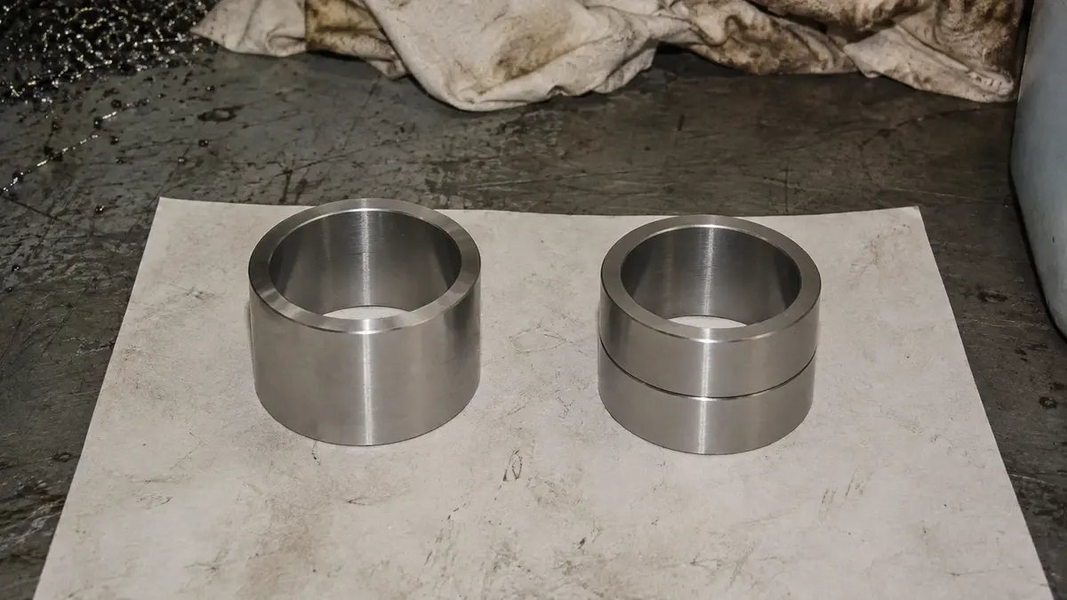
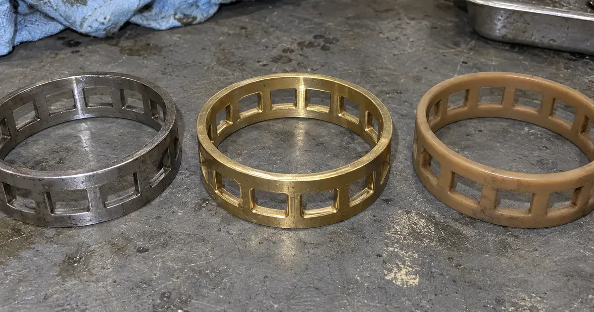
The cage material is the part of this choice that a specification actually has to name. Machined brass finger or window cages are the general default, with machined steel or steel pin-type construction for the largest sizes and the highest shock loads. The metallurgical argument behind that choice, including why a case-carburized ring behaves differently from a through-hardened one under impact, is set out in case-carburized against 52100 bearing steel.
What to Specify Beyond d × D × B
The envelope is the easy part. Clearance class, tolerance class, cage, and lubrication features are what decide whether the bearing survives a mill campaign.
| Property | Standard execution | Defined by |
|---|---|---|
| Dimensional tolerance | ISO class 6 (P6) | ISO 492 |
| Geometrical tolerance | ISO class 5 (P5) | ISO 492 |
| Radial internal clearance | C3 or C4 | ISO 5753-1 |
Radial internal clearance, feature G | C2 | ISO 5753-1 |
Standard executions per SKF (SKF). ISO 492 designates the radial tolerance classes Normal, 6X, 6, 5, 4 and 2; P6 and P5 are the corresponding DIN 620 suffix codes SKF uses for classes 6 and 5 (SKF).
That split between P6 dimensional and P5 geometrical tolerance is unusual, and it is deliberate. Geometrical accuracy governs running truth, which shows up directly in strip thickness and shape, so it gets the tighter class. Dimensional tolerance governs fit onto the neck and into the chock, where a slightly wider band is tolerable because the fit is engineered around it. American Roller Bearing reports C4 clearance with P5 accuracy as the common roll-neck supply condition, narrowing SKF's C3-or-C4 clearance range to C4 while retaining P5 running accuracy (American Roller Bearing).
Note that clearance values under ISO 5753-1 are valid for unmounted bearings at zero measuring load. The clearance you order is not the clearance you run. Interference fit on the neck consumes part of it, and thermal gradient across the bearing consumes more. The C3 and C4 radial internal clearance relationship between ordered and mounted clearance is where selection errors concentrate.
The G variant inverts the usual reasoning, which is worth understanding before you reject C2 as too tight. Feature G is a helical groove in the inner-ring bore, and bearings carrying it come as C2 rather than C3 or C4. That variant exists for loose-fit roll necks built for rapid roll changes. The looser fit consumes less clearance during mounting, so the bearing starts tighter to end up in the same place.
Beyond that, the loose-fit and lubrication feature set rarely appears in a competitor's write-up, and it belongs in an enquiry:
| Feature | Meaning |
|---|---|
G | Helical groove in the inner-ring bore |
W | Lubrication grooves in the ring side faces |
WI | Lubrication grooves in the inner-ring faces only |
WO | Lubrication grooves in the outer-ring faces only |
W20 | Lubrication holes in the outer ring |
W33 | Annular groove plus holes in the outer ring |
Source: SKF designs and variants (SKF).
A tapered bore is the other specification worth deciding early. Suffix K gives a 1:12 taper and K30 a 1:30 taper (SKF). Tapered-bore bearings mount with an interference fit that can be adjusted during mounting to a target radial internal clearance or a defined preload (SKF). American Roller Bearing offers the same two tapers for applications needing tighter control of mounted radial clearance (American Roller Bearing).
One related suffix is easy to miss at enquiry stage. If concentric grinding of the mounted inner race against the roll body is part of your build process, RG specifies a race with extra stock for that grinding.
On temperature, rings and rollers are heat stabilized to 150 °C and HNBR seals run from −40 to +140 °C, with the seal lip as the temperature peak in the assembly (SKF). Sealed designs use a spring-loaded double-lip HNBR seal and are limited by a permissible seal circumferential speed of 25 m/s (SKF). On a large-bore bearing that speed limit, not the bearing's own limiting speed, can be the binding constraint.
Load Ratings and Where They Stop Being the Limit
Both ratings scale with bore, but the static rating pulls away from the dynamic rating as the bearing grows. That is why shock rather than fatigue tends to govern selection at the large end.
ANDE's own published four-row cylindrical roller bearing range covers 34 sizes spanning a 145 to 900 mm bore. Across that range the basic dynamic radial load rating runs from 770 to 25,900 kN and the basic static radial load rating from 1,850 to 77,500 kN. Limiting speed under oil lubrication falls from 800 down to 170 rpm. Every figure in this section and the two charts below is taken from that table, for representative builds with a machined-brass cage at P5 precision.
The ratio of the two ratings is where the useful reading is, and it inverts the intuition an engineer carries over from small ball bearings. Dividing static rating by dynamic rating across the ANDE range gives a mean of about 2.2 below a 320 mm bore, rising to about 2.9 at 800 mm and above. Individual sizes scatter from 1.79 to 3.03, so this is a trend and not a formula.
Why the trend runs that way is straightforward once stated. Adding rows of longer rollers increases static contact area faster than it increases fatigue-limited dynamic capacity. Static capacity is governed by a permissible contact stress at a stationary contact. Dynamic capacity is governed by subsurface fatigue over millions of cycles. ISO 76 sets the contact-stress basis for the static rating, and the basic dynamic and static load ratings are calculated on different physical premises entirely. Practically: in a mill where the real threat is a shock event during bar entry or a roll change rather than accumulated running hours, C₀ is the number to size against.
Minimum load matters at the other end of the range and gets less attention than it deserves. A roller bearing that is too lightly loaded skids instead of rolling, which smears the raceway rather than fatiguing it. SKF's general rule is a minimum load of 0.02 C on roller bearings, with the accurate requirement given per product type (SKF). For four-row cylindrical roller bearings that requirement is a minimum radial load Frm computed from a minimum load factor, the bearing mean diameter and the rotational speed (SKF). Take the load factor from the current product table for the specific bearing rather than from a secondary source, because it is bearing-specific and misquoted often.
Mounting and the 90° Rotation Nobody Documents
Under a constant load direction only about a quarter of the outer ring ever carries load, so this bearing is built to be indexed in service. The indexing schedule belongs in the specification rather than in a technician's memory.
SKF sets out the practice in order. The outer-ring side faces are divided into four zones marked I to IV. Zone I additionally carries a line across the outside surface, so it can be found without reading the face. Zone I is positioned toward the load direction at initial mounting. The outer rings are then turned 90° after a period of service, and roughly 1,000 operating hours is the recommended interval before inspection (SKF).
There is a second marking rule that decides whether a roll change is survivable, and it is easy to get backwards. All components of one bearing are marked with the same serial number to prevent mixing. Inner rings and inner-ring pairs, however, are fully interchangeable and do not need to match the outer ring's serial number (SKF). That exception is what lets a mill keep spare inner rings mounted on necks in the roll shop and match them to whichever chock assembly comes off the stand. Treating the serial number as binding across all components would destroy that workflow for no engineering reason.
Interference fit on the roll neck is the norm, and the loose-fit case is the exception the G and W features exist to serve. American Roller Bearing's response to the same handling problem is a blended bevel on the inner-race leading edge. It eases the chock and outer-race roller assembly over a roll-mounted inner ring during robotic stand building or crane mounting (American Roller Bearing). The industry treats roll-change handling as a design problem, not just a procedural one.
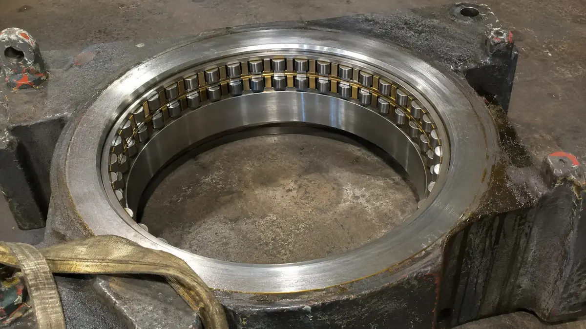
Installation damage is the failure mode this whole section prevents. For the damage patterns that follow a mishandled mount, see roll neck bearing damage patterns, and for pre-mount checks, verify the envelope before mounting.
Cross-Referencing Across SKF, NSK, Timken, and FAG
Bore and outside diameter usually carry across brands. Width and internal design frequently do not, so a crosswalk is a starting point and the chock drawing is the decision.
| ANDE | SKF | NSK | Timken | FAG | d × D × B |
|---|---|---|---|---|---|
| FCD145210155 | BC4-0101 | STF145RV2101g | 4R-7203 | FCD145210155 | 145 × 210 × 155 |
| FCD160230168 | BC4-0114 | STF160RV2302g | 4R-7204 | FCD160230168 | 160 × 230 × 168 |
| FCD220310192 | BC4-0117 | STF220RV3101g | 4R-7405 | FCD220310192 | 220 × 310 × 192 |
| FCDP380540400 | BC4B 320989/HA3 | STF380RV5402g | RYL 5404 | FCDP380540400 | 380 × 540 × 400 |
| FCD480680500 | 319320 | STF480RV6815g | 4R-9612 | FCD480680500 | 480 × 680 × 500 |
| FCD500700500 | 319254/VJ202 | STF500RV7011g | 4R-10010 | FCD500700500 | 500 × 700 × 500 |
| FCD650920670 | 239509 FA | STF650RV9212g | 4R-13209 | FCD650920670 | 650 × 920 × 670 |
| FCD8201100745 | BC4B 316341/HA4 | STF820RV1119g | RYL 1142 | FCD8201100745 | 820 × 1100 × 745 |
First-party ANDE cross-reference data. Confirm any interchange against the current OEM catalogue revision and the chock drawing before ordering.
Look at the first row. FCD145210155, BC4-0101, STF145RV2101g and 4R-7203 are four ways of writing one 145 × 210 × 155 envelope, and only one of them tells you the dimensions. The patterns at least let you identify the brand from the number. SKF uses drawing numbers and BC4 or BC4B prefixes. NSK uses STF…RV… with a trailing letter. Timken uses 4R-, with RYL and RXL on its long-product-mill line. FAG follows the FCD long form.
Here is the caveat that matters more than the table. SKF gives dimension standards for this bearing type as "Not standardized", qualified only by bore and outside diameter for many bearings following diameter series 9 or 0 of ISO 15 (SKF). ISO 15:2017 is a real and current standard covering preferred boundary dimensions for radial bearings of diameter series 7, 8, 9, 0, 1, 2, 3 and 4 (ISO 15). This bearing type simply is not fully inside it.
Note that the industry does not speak with one voice here. American Roller Bearing describes its four-row cylindrical bearings as industry interchangeable (American Roller Bearing). That is true at the level a distributor sells at, where many outer-race and inner-race configurations exist precisely to meet interchangeability requirements. SKF is describing the standards position. Both are accurate about different things, and the practical synthesis is narrower than either: d and D usually interchange, B and the internal design frequently do not.
So the interchange is dimensional. The differences that decide service life are cage type, clearance class, lubrication-groove pattern, and sealing, and none of those is visible in a part number crosswalk. Verify the spec, not the badge. SKF's Explorer four-row bearings, for example, are offered up to a 420 mm outside diameter and optimized for long product mills. They are fitted with two double prong-type brass cages, with steel cages available on request (SKF). That is a specification, and it is the kind of thing a crosswalk row cannot carry. For the method, see verifying a supplier's spec claims and the bearing manufacturer comparison.
If you have a chock drawing and a part number that disagree, send both. ANDE's four-row cylindrical roller bearings are quoted against the drawing and the operating spectrum, not against the number alone.
Frequently Asked Questions
Can a four-row cylindrical roller bearing take axial load?
No. SKF's equivalent load equations for this type are P = Fr for dynamic load and P₀ = Fr for static load, with no axial term in either. Any thrust in the position needs a separate thrust bearing. Some designs do accommodate axial displacement within defined limits with virtually no increase in friction. That is a different property, and it is why the type serves as the non-locating bearing in a mill stand. Displacement capacity is not load capacity.
What is the difference between FC, FCD, and FCDP?
Ring count and cage type, which together set the size range each design serves. FC has one inner ring and two outer rings. FCD has two inner and two outer rings, where split inner rings ease mounting on larger necks. FCDP adds a pin-type cage running pierced rollers, which fits more rollers and suits the largest necks and highest shock loads. Read the bore split as a tendency rather than a boundary: ANDE's own range includes an FCDP at a 380 mm bore, below the threshold distributor tables usually imply.
What clearance should I specify for a roll neck?
C3 or C4 per ISO 5753-1 are SKF's standard executions for this bearing type, and C4 with P5 accuracy is the common roll-neck supply condition reported by American Roller Bearing. C2 applies to bearings with feature G, a helical groove in the inner-ring bore, which serves loose-fit necks built for rapid roll changes. Remember that ISO 5753-1 values apply to unmounted bearings at zero measuring load, so interference fit and thermal gradient both consume clearance before the bearing runs.
How do I read an FCD bearing number?
Two systems are in circulation. The short catalogue form multiplies the first two digit groups by five and reads the remaining group as width, so FC 2942155 is 145 × 210 × 155. The long form spells the millimetres out, so FCD145210155 is the same 145 × 210 × 155. Note that these are the same envelope written two ways, and the load ratings published against that envelope disagree between sources, so neither notation tells you which internal design or rating basis you are buying. An SKF drawing number such as 319254/VJ202 is not decodable at all.
Why do these bearings need to be rotated in service?
Because under a constant load direction only about a quarter of the outer ring ever carries load, so three quarters of the raceway sits idle while one quadrant accumulates all the damage. SKF divides the outer-ring side faces into four zones marked I to IV. Zone I also carries a line across the outside surface, and it is positioned toward the load direction at first mounting. Turning the outer rings 90° after a period of service redistributes the duty, and roughly 1,000 operating hours is the recommended interval before inspection.
Specifying One Without Guessing
Four-row cylindrical roller bearings reward a specification that goes past the envelope, and they punish one that stops there.
- Treat the part number as an identifier, not a description. A drawing number carries no design information, and the two decodable notations encode the envelope only.
- Size against C₀, not just C, at large bores. The static rating pulls away from the dynamic rating as the bearing grows, and shock rather than fatigue is usually what ends a roll-neck bearing.
- Name the clearance class, the tolerance class, the cage, and the lubrication features in the enquiry. Those decide service life and none of them appears in a crosswalk.
- Plan the indexing schedule with the bearing. The four-zone marking and the 90° rotation are part of the specification, not an optional maintenance habit.
- Verify width and internal design against the chock drawing. Bore and outside diameter usually carry across brands; the rest frequently does not.
Send the chock drawing alongside the part number you are holding, in whichever notation you have it. ANDE will cross-reference the four-row cylindrical roller bearing range against the drawing, the clearance requirement, and the operating spectrum, and say plainly where an envelope match is not a functional match.
About the Author
Jeff Li writes on bearing engineering and global sourcing for ANDE Bearing. He works directly with OEM and aftermarket buyers in automotive, heavy industry, and renewable energy. Connect on LinkedIn.