The basic dynamic load rating (C) is the load a rolling bearing can carry for one million revolutions with 90% reliability — it governs fatigue life when the bearing rotates. The basic static load rating (C₀) is the load that produces a permanent deformation of just 0.0001 × the rolling-element diameter at the most heavily loaded contact — it governs the bearing when it is stationary, oscillating, or rotating very slowly. Confuse the two and you either oversize a fatigue-driven bearing or undersize one that is actually being brinelled at standstill.
This guide explains both ratings the way the ISO 281 and ISO 76 standards define them, walks through the formulas every bearing engineer uses (L₁₀ fatigue life and s₀ static safety factor), and shows how to apply them to the bearings used in real industrial machinery — wind turbines, slewing rings, gearboxes, mills, and motors.
Key Takeaways
- Dynamic load rating C is for rotating bearings; static load rating C₀ is for stationary, oscillating, or very-slow-rotating bearings.
- ISO 281 defines L₁₀ = (C / P)ᵖ with p = 3 for ball bearings and p = 10/3 for roller bearings (cylindrical, tapered, spherical, needle).
- ISO 76 defines C₀ by a permanent-deformation criterion of 1/10,000 of the rolling-element diameter at the most heavily loaded contact.
- Static safety factor s₀ = C₀ / P₀ must typically be ≥ 1 for ball bearings under normal load, ≥ 1.5 for normal roller bearings, and ≥ 3 for roller bearings under shock loads.
- Below roughly 10 rpm, oscillating, or at standstill, C₀ — not C — is the rating that controls.
- Comparing C across ball and roller bearings of the same bore is misleading because the L₁₀ exponent differs.
What Is the Dynamic Load Rating (C) of a Bearing?
The basic dynamic load rating C is defined by ISO 281:2007 as the constant radial (or axial) load a group of identical bearings can theoretically endure for one million revolutions before 10% of them fail by rolling-contact fatigue. It is the input to every fatigue-life calculation in a rotating machine and the figure stamped at the top of every catalogue page next to the bore.
C is not a maximum load. It is a reference load tied to a specific reliability (90%) and a specific number of revolutions (10⁶). The actual life of a bearing under a different load P follows the L₁₀ formula:
L₁₀ = (C / P)ᵖ millions of revolutions, where p = 3 for ball bearings and p = 10/3 for roller bearings (Timken Engineering Manual, Order No. 10424, "Bearing Life Equations").
That exponent is the single most important number in bearing sizing. A 25% reduction in load roughly doubles ball-bearing life and almost triples roller-bearing life — which is why oversizing a bearing pays back so quickly when the application is fatigue-limited.
The asymmetry that surprises new bearing engineers. The same 25% load swing produces a different life ratio on each side of the design point because the exponent operates on a load ratio, not a delta. Cutting load by 25% (new load = 0.75 × P) takes ball-bearing life to (1/0.75)³ ≈ 2.37× rated and roller-bearing life to (1/0.75)^(10/3) ≈ 2.61× rated. But increasing load by 25% (new load = 1.25 × P) takes ball life to 0.8³ ≈ 0.51× and roller life to 0.8^(10/3) ≈ 0.48× of rated. Rollers give more life back when you derate, and they also lose slightly more when the operating load creeps above design — a dual reason the heavy-industry rule of thumb is to size rollers conservatively rather than to nominal L₁₀.
The dynamic equivalent load P combines radial and axial components into a single equivalent radial figure: P = X · Fᵣ + Y · Fₐ. The X and Y factors come from the catalogue page and depend on the bearing type and the Fₐ / Fᵣ ratio.
What Is the Static Load Rating (C₀) of a Bearing?
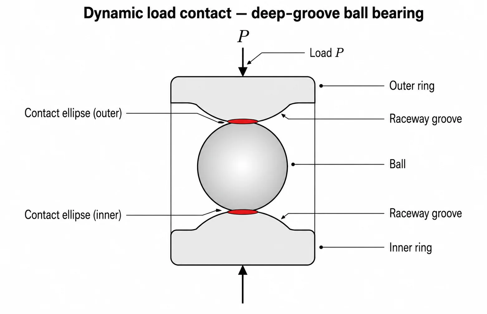
The basic static load rating C₀ is defined by ISO 76:2006 as the load that produces a calculated permanent deformation at the most heavily loaded rolling-element-to-raceway contact equal to 1/10,000 of the rolling-element diameter Dw (0.0001 × Dw). At that load, the bearing has not yet failed — but it is at the edge of measurable plastic flow at the contact point.
In most major brand catalogues, this deformation criterion corresponds to a maximum Hertzian contact stress of 4,200 MPa for ball bearings and 4,000 MPa for roller bearings (SKF size selection based on static load; also Timken Engineering Manual, "Static Load Rating," p. 47). For self-aligning ball bearings, the lower contact conformity allows a higher reference stress of 4,600 MPa per ISO 76; the catalogue C₀ value already accounts for it, so designers should use the published number directly.
Static load rating matters whenever the bearing is not rotating fast enough to spread the load over many contact points — at standstill under heavy load, in oscillating motion (pitch bearings on wind turbines, machine-tool indexers), or at rotational speeds below roughly 10 rpm where the same rolling element sees the same azimuth for many seconds at a time.
The static equivalent load P₀ uses different X₀ and Y₀ factors than the dynamic P. Reusing the dynamic factors in a static check is one of the most common mistakes in bearing-sizing spreadsheets — Timken's manual lists separate X₀ / Y₀ tables on p. 45 specifically because they differ.
Dynamic vs Static Load: Side-by-Side Comparison
The cleanest way to keep the two ratings straight is the table below. Every catalogue lists both, and both are needed for any bearing that sees both running and standstill conditions in service.
| Property | Dynamic load rating C | Static load rating C₀ |
|---|---|---|
| Standard | ISO 281:2007 | ISO 76:2006 |
| What it governs | Rolling-contact fatigue life under rotation | Permanent deformation at standstill / very slow motion |
| Failure mode at the limit | Sub-surface fatigue spalling | Brinelling (plastic indentation of the raceway) |
| Reference condition | 10⁶ revolutions, 90% reliability | Permanent deformation = 0.0001 × rolling-element diameter |
| Typical contact stress at rating | n/a — life-based | ~4,200 MPa (ball) / ~4,000 MPa (roller) |
| Equivalent load formula | P = X · Fᵣ + Y · Fₐ | P₀ = X₀ · Fᵣ + Y₀ · Fₐ |
| Sizing equation | L₁₀ = (C / P)ᵖ | s₀ = C₀ / P₀ |
| When it governs | Continuous rotation above ~10 rpm | Standstill, oscillation, rotation < 10 rpm, or shock loads |
How Do You Calculate Bearing Life from the Dynamic Load Rating?
Bearing life under a known operating load P and rotational speed n (rpm) is calculated from the L₁₀ formula in ISO 281:
- L₁₀ = (C / P)ᵖ — life in millions of revolutions
- L₁₀ₕ = L₁₀ · 10⁶ / (60 · n) — life in operating hours (equivalently, (10⁶ / (60 · n)) · (C / P)ᵖ)
For a deep-groove ball bearing with C = 35.1 kN, operating under a steady radial load P = 7 kN at n = 1,500 rpm:
- L₁₀ = (35.1 / 7)³ ≈ 126 million revolutions
- L₁₀ₕ = (10⁶ / (60 × 1,500)) × 126 ≈ 1,400 hours
The chart below makes the exponent's effect explicit: a roller bearing (p = 10/3) gains life faster than a ball bearing (p = 3) as C/P increases. The vertical axis is logarithmic — at C/P = 8, a roller bearing's L₁₀ is roughly twice that of a ball bearing with the same C/P ratio.

That basic L₁₀ figure is then refined by the modified rating life equation introduced in ISO 281:2007: Lₙₘ = a₁ · aISO · L₁₀, where a₁ adjusts for reliability higher than 90% and aISO corrects for lubrication condition, contamination, and the bearing's fatigue load limit Cᵤ.
Standard reliability factors a₁ from ISO 281:2007, Table 1 (also reproduced in the Timken Engineering Manual, Table 11):
| Reliability | a₁ | Life designation |
|---|---|---|
| 90% | 1.00 | L₁₀ |
| 95% | 0.64 | L₅ |
| 96% | 0.55 | L₄ |
| 97% | 0.47 | L₃ |
| 98% | 0.37 | L₂ |
| 99% | 0.25 | L₁ |
| 99.9% † | 0.093 | L₀.₁ |
† The 99.9% row is not part of the ISO 281:2007 normative table, which stops at 99%. Manufacturer literature (SKF, Timken, NSK) extends the curve to L₀.₁ using a Weibull-slope extrapolation; cite it as a manufacturer convention rather than as ISO data.
A wind-turbine main bearing or a paper-machine roll bearing routinely targets 99% reliability — that a₁ = 0.25 is why catalogue L₁₀ numbers look so optimistic compared with what design engineers actually use in service-life models.
How Do You Calculate the Static Safety Factor s₀?
The static safety factor compares the catalogue static rating to the actual maximum load the bearing will see:
s₀ = C₀ / P₀
ISO 76:2006 defines C₀ and the s₀ concept but does not publish a normative table of minimum safety factors — it directs designers to the bearing manufacturer's catalogue. The major brand catalogues (SKF General Catalogue, NSK Cat. E1102, Schaeffler HR1), applying ISO 76, converge on the minimum s₀ values below. Use this table as a quick reference whenever you need to size against C₀:
| Bearing type | Light / smooth load | Normal operation | Heavy shock or vibration |
|---|---|---|---|
| Ball bearings | s₀ ≥ 0.5 | s₀ ≥ 1.0 | s₀ ≥ 1.5 |
| Roller bearings | s₀ ≥ 1.0 | s₀ ≥ 1.5 | s₀ ≥ 3.0 |
Roller bearings are held to a higher s₀ than ball bearings because the line contact concentrates load over a smaller area, making them more sensitive to brinelling at the same nominal load. For very slow rotation or pure oscillation — pitch bearings on a wind turbine, the slewing ring on an excavator, the indexing bearing on a machine-tool turret — s₀ ≥ 2 is typical, with values of 4 or higher used where very low static deformation is critical (high-precision indexing, large slewing rings under combined moment loading).
When Does the Static Rating Actually Govern?
A useful design rule, repeated across the SKF, NSK, and Schaeffler general catalogues, is that below roughly 10 rpm — or under any oscillating motion — fatigue is no longer the dominant failure mode and the static rating C₀ takes over as the sizing constraint. The exact threshold varies by manufacturer (Schaeffler and NSK sometimes use 6 rpm, older SKF editions 10 rpm), so consult the specific catalogue you are sizing from. The same principle applies whenever a bearing carries shock loads at standstill, even if it normally rotates faster.
Examples of bearings where C₀ governs:
- Slewing bearings on cranes, excavators, and wind-turbine yaw systems — typically rotate at fractions of an rpm under heavy combined loads.
- Wind-turbine pitch bearings — oscillate continuously through a few degrees, never completing a full revolution.
- Construction-machine kingpin bearings — load cycles dwarf rotation count.
- Antenna and radar pedestals — long dwell at fixed azimuth under wind load.
- Kiln and furnace support rollers — rotate slowly enough that fatigue cycles accumulate over decades, but standstill load can brinell.
Conversely, C governs for the bearings most engineers picture first: electric-motor bearings spinning at 1,800–3,600 rpm, gearbox shaft bearings, machine-tool spindles, automotive wheel bearings, and rolling-mill work-roll bearings spinning continuously under their primary radial load.
Six Common Mistakes Engineers Make With C and C₀
These are the failure modes that show up in bearing post-mortems and warranty claims most often. Each one is documented in major-brand technical literature and in field-failure reports.
1. Sizing a slewing bearing with C instead of C₀. Slow-rotating slewing rings fail by raceway brinelling long before fatigue accumulates. Specifying based on L₁₀ gives an artificially generous-looking life and an undersized bearing.
2. Ignoring shock-load s₀ on roller bearings. Crushers, presses, mill back-up rolls, and impact loaders need s₀ ≥ 3 per ISO 76 and the major brand catalogues. Sizing to s₀ ≈ 1 invites raceway indentation on the first hard cycle.
3. Comparing C across bearing types of the same bore. A cylindrical roller bearing and a deep-groove ball bearing with the same bore can have very different C values and a different L₁₀ exponent (10/3 vs 3). Equal C does not mean equal life under the same load.
4. Using catalogue C without the aISO modifier. Real-world lubrication, contamination, and Cᵤ (fatigue load limit) push L₁₀ well below the catalogue value. ISO 281:2007 introduced aISO exactly to correct this; ignoring it produces life predictions that are routinely 2–10× optimistic.
5. Reusing dynamic X / Y factors in the P₀ calculation. X₀ and Y₀ (Timken Engineering Manual Table 9) differ from the dynamic X / Y. Reusing the dynamic factors silently miscalculates the static check.
6. Treating wind-turbine pitch bearings as fatigue-driven. Pitch bearings oscillate through a few degrees thousands of times per day. Their failure mode is false-brinelling and fretting corrosion, not classical fatigue. NREL technical reports on wind-turbine pitch-bearing failures point to this misunderstanding repeatedly.
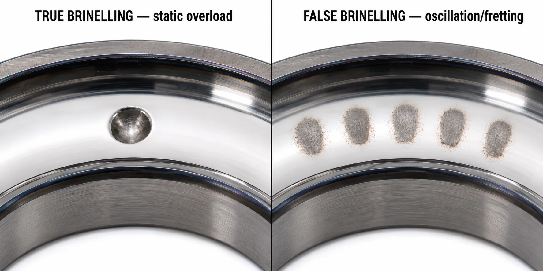
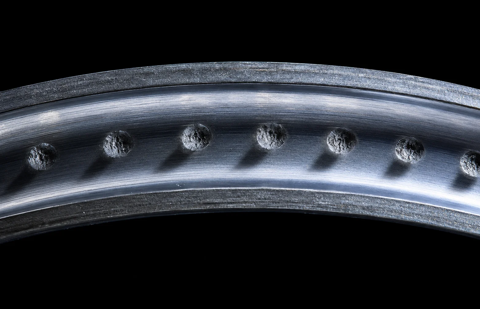
True Brinelling vs False Brinelling — Two Failure Modes, Two Rating Domains
It is worth distinguishing the two failure modes that get loosely called "brinelling," because they sit in different rating domains:
- True brinelling is a static-load failure. A single overload event plastically dents the raceway at the rolling-element contact — exactly the deformation that C₀ (per ISO 76, the 1/10,000 × Dw criterion) is set to bound. A high s₀ protects against it.
- False brinelling is an oscillation/vibration failure. It is not a single-event dent at all: it is mechanical micro-wear of the surface caused by repeated micro-movements under cyclic vibration without sufficient hydrodynamic film replenishment. The marks look like brinell impressions but are wear scars, not plastic deformation. Specifying for C₀ alone does not protect against it; lubrication strategy, grease selection, and start-up cycling protocols do.
Worked Example — Dynamic and Static Check on the Same Bearing
A spherical roller bearing on a paper-machine drying-cylinder shaft has the following catalogue ratings:
- C = 670 kN (basic dynamic load rating)
- C₀ = 1,020 kN (basic static load rating)
Operating conditions:
- Nominal radial load Fᵣ = 180 kN
- Axial load Fₐ = 35 kN
- Rotational speed n = 250 rpm
- Catalogue X = 1, Y = 2.5; X₀ = 1, Y₀ = 2.7
- Maximum shock-load radial component during sheet break: Fᵣ,ₘₐₓ = 320 kN
Note on X = 1. Fₐ / Fᵣ = 35 / 180 ≈ 0.19, just below this bearing's catalogue e threshold. For spherical roller bearings, e typically falls in the 0.2–0.4 range depending on series, so this ratio is borderline — always verify the catalogue e page for the specific bearing rather than assuming X = 1. For higher Fₐ / Fᵣ ratios, spherical roller bearings switch to X ≈ 0.67.
Dynamic check (rotation):
P    = X · F_r + Y · F_a       = 1 × 180 + 2.5 × 35 = 267.5 kN
C/P  = 670 / 267.5             ≈ 2.505
p    = 10 / 3                  ≈ 3.333   (roller-bearing exponent)
L10  = (C/P)^p = 2.505^3.333   ≈ 21.4 million revolutions
L10h = 10^6 / (60 · n) · L10
     = 10^6 / (60 · 250) · 21.4
     ≈ 1,427 hours
That is far below the paper-machine industry target of roughly 100,000 hours for continuous-operation drying-cylinder bearings — the candidate bearing delivers about 1.4% of the expected service life. The real number after aISO is even lower, signaling the bearing is severely undersized for fatigue or that lubrication needs significant improvement.
Static check (shock event):
P0   = X0 · F_r,max + Y0 · F_a = 1 × 320 + 2.7 × 35 = 414.5 kN
s0   = C0 / P0 = 1,020 / 414.5 ≈ 2.46
For a roller bearing under shock loads, the major bearing manufacturer guidelines (SKF, NSK, Schaeffler, Timken — applying ISO 76 context) recommend s₀ ≥ 3. The candidate bearing's s₀ ≈ 2.46 sits below that threshold, putting it at risk of raceway brinelling on a sheet-break shock event — even though, on paper, the dynamic catalogue rating looks comfortable. This is exactly the failure mode covered in our technical teardown on hot strip mill bearing failure analysis: the bearing meets its dynamic life target but fails statically under transient overload.
Sizing up by one bore class — to a 240-series spherical roller bearing with, for example, C₀ ≈ 1,290 kN — gives s₀ = 1,290 / 414.5 ≈ 3.11, which clears the ≥ 3 shock-load threshold. Alternatively, specifying a higher-C₀ internal design within the same envelope (heavier rollers, optimized internal geometry) achieves the same restoration of the safety margin without increasing the bore diameter.
What we see in paper-machine warranty returns. Of the spherical roller bearings returned from drying-cylinder positions in the last twelve months, the largest single root-cause cluster was raceway brinelling traceable to a sheet-break overload, not fatigue spalling. In every one of those cases the original sizing calculation had cleared the dynamic L₁₀ check comfortably (often C/P > 2.5) but had been done with a static safety factor below 3 because the spec sheet listed only steady-state loads, not the transient peak. Asking for the worst-case shock load up front, then running the s₀ check against it, would have caught all of them on paper before the bearing was even ordered.
FAQ
Q: What is the difference between basic and modified rating life?
Basic rating life L₁₀ assumes 90% reliability and ideal lubrication and cleanliness. Modified rating life Lₙₘ = a₁ · aISO · L₁₀ (per ISO 281:2007) corrects for higher reliability targets and for actual operating lubrication, contamination, and fatigue-load-limit conditions. Real-world design always uses the modified figure.
Q: Can a bearing's static load rating be higher than its dynamic rating?
It depends on the bearing type — C₀ is not universally larger than C. For most deep-groove ball bearings, C₀ is actually smaller than C: the SKF 6205, for example, lists C = 14.8 kN and C₀ = 7.8 kN. For cylindrical roller bearings, the two values are often similar (NU 205: C ≈ 28.6 kN, C₀ ≈ 27 kN — representative values; verify against the selected manufacturer's catalogue, since exact numbers vary slightly by brand and cage type). For spherical roller bearings, C₀ tends to be modestly higher than C — the SKF 22220 E lists C = 387 kN and C₀ = 450 kN, a ratio of about 1.16. Large slewing rings and some thrust bearings can show C₀ substantially above C.
The reason for the type-dependent split is contact geometry. Ball bearings make point contact with the raceway, concentrating localized Hertzian stress on a tiny patch — when the bearing is stationary, that point contact pulls the static rating down relative to the rolling-fatigue rating. Roller bearings make line contact, which distributes static load across a much larger area and lifts C₀ relative to C. The takeaway: C and C₀ answer different design questions and cannot be compared as a generic "higher" or "lower" — always read both directly off the catalogue page.
Q: How does the L10 exponent affect bearing selection between ball and roller types?
The exponent p in L₁₀ = (C / P)ᵖ is 3 for ball bearings and 10/3 for roller bearings. Roller bearings are more sensitive to load: doubling the load reduces ball-bearing life by 8× but reduces roller-bearing life by about 10×. That higher sensitivity is one reason roller bearings tend to be sized more conservatively than ball bearings of equivalent C.
Q: What is the fatigue load limit Cu and why does it matter?
Cᵤ is the fatigue load limit — the load below which, in theory, a perfectly clean and well-lubricated bearing experiences no fatigue damage. It is published for every bearing in modern catalogues and is the dividing line in the ISO 281 aISO calculation between bounded life and infinite-life behavior. Designs operating well below Cᵤ in clean, well-lubricated conditions can run effectively without a fatigue limit.
Q: How do dynamic and static ratings apply to oscillating bearings?
Oscillating bearings (small-amplitude back-and-forth motion, never completing a revolution) are a special case. The L₁₀ formula does not apply directly because no rolling element sees a fresh contact path. The static rating C₀ governs, and false-brinelling becomes the dominant failure mode. ISO 281 and the major catalogues provide adjusted formulas for oscillating bearings, but the design starting point is s₀, not L₁₀.
Q: Are dynamic and static ratings the same in ABMA and ISO standards?
The two systems are aligned in concept but diverge slightly in coefficients. ISO 281 corresponds to ABMA Std. 9 (ball bearings) and ABMA Std. 11 (roller bearings); ISO 76 corresponds to ABMA's static-rating standard. Most catalogue values from major manufacturers list both, and the differences are small enough that for engineering design either system is acceptable provided you stay consistent within a single calculation.
Conclusion
Dynamic load rating C and static load rating C₀ answer two completely different questions about the same bearing. C tells you how long the bearing will run under a given load before fatigue spalling shows up; C₀ tells you whether a stationary or slowly-moving bearing will brinell under peak load. Both are published on every catalogue page. The mistake is using only one.
The right discipline is the one practised by every well-run bearing application engineering group: run both checks for any bearing that sees both rotation and standstill conditions, use the modified rating life Lₙₘ with realistic aISO for the dynamic calculation, and apply the brand-specific s₀ table from ISO 76 for the static check — with extra margin for shock loads on roller bearings.
If you are sizing a bearing for a heavy industrial application — a rolling mill, a wind turbine, a paper machine, or any equipment that mixes high speed and shock-load standstill — and want a second opinion before the order goes out, ANDE Bearing's technical team works through these calculations with customers daily. Send the application data and we will return both the L₁₀ and the s₀ figures on the candidate bearings.
For background on the bearing types referenced in this guide, explore our comprehensive guide to the different kinds of bearings used in heavy machinery, our deep-dive on tapered vs cylindrical roller bearings for rolling-mill roll necks, and our analysis of spherical roller bearings in misalignment-prone heavy industry.
About the Author
Jeff Li writes on bearing engineering and applications for ANDE Bearing. Connect on LinkedIn.