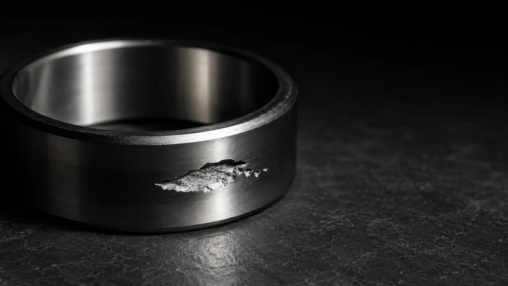
A bearing sits on the bench with a mark on the raceway, and the replacement goes into the same machine on Monday. Naming that mark is the only thing standing between one failure and two.
Begin with the number that reframes the problem. Roughly 0.5% of bearings are replaced because they were damaged or failed, while about 90% outlive the equipment they were fitted to (SKF, PUB 14219/3). Failure is the exception. A failed bearing is usually telling you something about the application, not about the part.
Two things make that message hard to read. The statistics people quote contradict each other, because they count different populations. And the damage has competing vocabularies, so one mark is called spalling, flaking, or pitting depending on whose chart you are holding.
This guide gives the six ISO 15243 modes with their real clause numbers, reconciles the statistics by denominator, cross-walks the naming systems, and turns each appearance into a specification or installation fix.
Key Takeaways
- Most bearings never fail. SKF puts about 90% as outliving their equipment, 9.5% as replaced preventively, and roughly 0.5% as replaced for damage or failure.
- Ask what the denominator is before quoting a percentage. "36% lubrication" counts causes in bearings SKF inspected. "0.5%" counts all bearings in service. The two are not comparable.
- ISO 15243:2017 classifies six failure modes by appearance, not by cause: rolling contact fatigue (5.1), wear (5.2), corrosion (5.3), electrical erosion (5.4), plastic deformation (5.5), cracking and fracture (5.6).
- In SKF's inspection data, classic fatigue is 2% of damage causes. Lubrication, contamination, handling and mounting account for about three quarters.
- A 10% load overshoot costs about 25% of calculated life, because L₁₀ scales with (C/P)³ for ball bearings under ISO 281.
- Some premature failures fall outside the six modes. White etching cracks are, on SKF's published position, a consequence rather than a root cause.
How Often Do Bearings Actually Fail?
Most bearings outlive the machine. SKF's failure-analysis handbook splits the whole installed population three ways (SKF, PUB 14219/3):
- About 90% outlive the equipment they are installed in.
- About 9.5% are replaced before failure, for preventive reasons.
- Approximately 0.5% are replaced because they are damaged or fail.
Schaeffler/FAG reaches the same order of magnitude from a different dataset. Its damage publication states that "only about 0.35% of all rolling bearings do not reach expected life" (Schaeffler/FAG, Rolling Bearing Damage, WL 82 102/3). That figure's underlying chart cites antriebstechnik 18 (1979), so read it as a long-standing industry benchmark rather than current data.
Two independent makers agreeing that well under 1% of bearings fail should change how you read a failure. It is an outlier event, and outliers have specific assignable causes.
The denominator problem
Here is where nearly every article on this topic goes wrong. At least four different percentages circulate as if they answered the same question. They do not.
All bearings in service. About 0.5% get replaced for damage or failure (SKF). This is the number that tells you failure is rare.
Causes of damage in bearings that were inspected. SKF logs its inspections in a tool called BART. The cause distribution it reports is lubrication 36%, contamination 23%, application 18%, mounting interface 8%, handling 8%, electrical 5% and fatigue 2% (SKF Evolution). This is the number that tells you what to fix.
ISO failure modes identified in those same inspections. The five most common are abrasive wear (26%), surface initiated fatigue (16%), moisture corrosion (14%), adhesive wear (7%) and current leakage erosion (7%). Together they account for about 70% of all modes identified (SKF Evolution, 2022). This is the number that tells you what the damage looks like.
Why the bearing was pulled off the machine. Also from BART: excessive vibration 32%, excessive noise 23%, removed for maintenance reasons 12%, excessive temperature 11%, seizure 9%, and a tail of smaller reasons (SKF Evolution, 2022). This is the number that tells you what the operator noticed. Because more than half of removals start with a symptom an operator can hear or feel, our guide to bearing noise covers how to attribute that symptom before pulling the bearing.
Note what panels B and C do to the word "fatigue". As a cause, fatigue is 2%. As a mode, surface initiated fatigue is 16%. Both come from the same inspection dataset. The gap opens because surface initiated fatigue is usually the visible end state of a lubrication or contamination problem. The same bearing gets counted as a lubrication cause and a fatigue mode. That one discrepancy is the whole argument for keeping mode and cause separate.
SKF's own cause rules of thumb also disagree with each other, which is worth knowing before you cite one. The current handbook says roughly 1/3 lubrication, 1/3 contamination, 1/4 application and mounting, with no fatigue category at all (PUB 14219/3, 2025). An SKF training transcript gives 1/3 fatigue, 1/3 lubrication, 1/6 contamination, 1/6 other (SKF Aptitude transcript R32). SKF notes in both that the split shifts by industry, and gives pulp and paper as a case where contamination and inadequate lubrication dominate rather than fatigue.
Two caveats to carry forward. SKF publishes no sample size and no collection period for the BART percentages, so treat them as a large maker's inspection experience rather than a controlled study. And "bearings SKF inspected" is a biased sample by construction, because nobody sends in a bearing that is running fine.
For the lubrication share in depth, including why the widely repeated "80% of failures are lubrication" figure answers a different question again, see the lubrication pillar.
The Six ISO 15243 Failure Modes
ISO 15243:2017 sorts in-service bearing damage into six modes by appearance, each with its own clause number: rolling contact fatigue (5.1), wear (5.2), corrosion (5.3), electrical erosion (5.4), plastic deformation (5.5), and cracking and fracture (5.6). Those six contain 14 submodes, and the submode clause numbers are the precise way to record a finding.
5.1 Rolling contact fatigue splits into subsurface initiated (5.1.2) and surface initiated (5.1.3). Subsurface initiated fatigue is the mechanism the L₁₀ rating life predicts, driven by cyclic stress below the surface, often starting at an inclusion. Under temporary overload or another material-weakening event, that life collapses to 5% to 10% of L₁₀mh (SKF Evolution). Surface initiated fatigue (5.1.3) starts at the rolling surface instead, caused by surface distress from an inadequate lubricant film or poor cleanliness.
5.2 Wear splits into abrasive (5.2.2) and adhesive (5.2.3). Abrasive wear is progressive material removal, usually with particle contamination or inadequate lubrication present, and it leaves surfaces looking dull. Adhesive wear transfers material between sliding surfaces and appears as smearing or galling, typically when a bearing is too lightly loaded or a rolling element accelerates hard entering the load zone.
5.3 Corrosion covers moisture corrosion (5.3.2), fretting corrosion (5.3.3.2) and false brinelling (5.3.3.3). Fretting corrosion arises from micromovement at a fit interface and shows as red or blackish oxidation at the bore or housing seat. False brinelling is wear at rolling-element spacing caused by small oscillation or vibration, and it removes the original manufacturing finish.
5.4 Electrical erosion covers two intensities. Excessive current erosion (5.4.2) resembles arc welding and leaves tempered, rehardened or remelted craters. Current leakage erosion (5.4.3) leaves small adjacent craters and a grey washboard pattern over time.
5.5 Plastic deformation covers overload deformation (5.5.2), which is true brinelling from static overload, hammering or a drop, and indentations from particles (5.5.3). SKF notes that subsequent overrolling of a particle indentation can lead to surface initiated fatigue at 5.1.3, which is how a contamination event becomes a fatigue mode.
5.6 Cracking and fracture covers three routes. Forced fracture (5.6.2) usually comes from excessive interference fit, or from driving a tapered-bore bearing too far up its seat. Fatigue fracture (5.6.3) comes from cyclic bending, and thermal cracking (5.6.4) from frictional heat in sliding contact.
The standard's scope matters as much as its content. ISO 15243 classifies failure modes occurring in service, and its stated purpose is to help identify modes based on appearance. It is a naming and description system, not a root-cause procedure, and it does not cover manufacturing defects.
Cross-walk: one mark, several vocabularies
An engineer typically holds an ISO clause number, a Japanese maker's catalogue table, and shop-floor vernacular, with no map between them. The table below is that map. The ISO and Koyo/JTEKT columns are the published terms from each system; the last column is field vernacular, included because it is what gets written on the work order.
| ISO 15243 clause | ISO / SKF term | Koyo/JTEKT term | Commonly called |
|---|---|---|---|
| 5.1.2 | Subsurface initiated fatigue | Flaking (spalling) | Spalling, pitting |
| 5.1.3 | Surface initiated fatigue | Flaking (spalling) | Micropitting, frosting, peeling |
| 5.2.2 | Abrasive wear | Wear | Dull or sanded raceway |
| 5.2.3 | Adhesive wear | Smearing, scuffing | Smearing, galling, skidding |
| 5.3.2 | Moisture corrosion | Rust, corrosion | Rust, water damage |
| 5.3.3.2 | Fretting corrosion | Fretting, creep | Red oxide at the fit, bore fretting |
| 5.3.3.3 | False brinelling | Brinelling | Transit marks, standstill washboard |
| 5.4.2 | Excessive current erosion | Electric pitting | Arc burns, weld craters |
| 5.4.3 | Current leakage erosion | Electric pitting | Fluting, washboarding |
| 5.5.2 | Overload deformation | Brinelling, nicks | True brinelling, dented raceway |
| 5.5.3 | Indentations from particles | Nicks, scratching | Debris dents |
| 5.6.2 | Forced fracture | Cracking, chipping | Cracked or split ring |
| 5.6.3 | Fatigue fracture | Cracking | Cracked ring |
| 5.6.4 | Thermal cracking | Cracking, discoloration | Heat cracks |
Koyo/JTEKT's own list runs to 12 numbered types and includes categories ISO distributes elsewhere, such as creep, pear skin, seizure and cage damage (Koyo/JTEKT). Cage damage is worth treating as a symptom rather than a mode, and our guide to bearing cages works through NSK's condition-to-cause matrix for it. Timken publishes a third vocabulary on its damage-analysis poster. None of these is wrong. They are simply different classification systems, which is why quoting a clause number travels better than quoting a name. For ISO 15243 applied end to end on a single asset, see the failure analysis on a hot strip mill roll neck.
Reading the Damage: From Pattern to Root Cause
The damage pattern gives you the mode. The mode plus the operating context gives you the cause. SKF states the priority plainly: "It is also important, and perhaps more important, to understand what caused the failure than the failure mode itself" (SKF Evolution). Skipping the second step is how a replacement bearing fails the same way.
Work in this order.
1. Look at the lubricant before you clean anything. Colour, smell, free water, metal content. Take a sample and compare it against fresh product. Washing a bearing you intend to diagnose destroys evidence.
2. Locate the damage relative to the load zone. A circumferential band on the inner ring with a localized patch on the outer ring is the normal rotating-inner-ring pattern. Damage evenly spaced at rolling-element pitch points to brinelling, true or false. Uniform marks across the full raceway width point to current.
3. Read the surface finish inside the mark. This is the test that separates the two most confused modes. True brinelling (5.5.2) is plastic deformation, so material is displaced rather than removed and the original ground finish is generally still readable inside the depression. False brinelling (5.3.3.3) is wear, and SKF notes it "removes the original manufacturing finishes of the surfaces", often leaving red or blackish oxidation. One is a load and mounting problem, the other a vibration and storage problem, and the fixes have nothing in common.
4. Check the seats. Red or blackish oxide powder at the bore or housing fit indicates fretting corrosion and a fit too loose for the load and rotation case. SKF notes fretting corrosion appears in most bearings to some degree, so judge severity rather than presence.
5. Check the drive. A grey washboard pattern on a motor bearing fed by a variable-frequency drive is current leakage erosion, not mechanical wear.
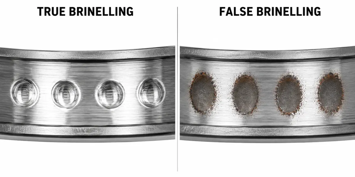
Step 3 is worth seeing rather than reading. Both sets of marks above sit at rolling-element spacing, so the spacing is not the tell. The finish inside the mark is: grinding lines still running through the dent on the left, finish worn away and oxide at the rim on the right.
| Appearance | Likely ISO mode | Typical cause | First thing to change |
|---|---|---|---|
| Dull, matte raceway, geometry lost | Abrasive wear (5.2.2) | Particle ingress or lubricant starvation | Sealing and filtration, relubrication interval |
| Evenly spaced dents, ground finish still visible | Overload deformation (5.5.2) | Static overload, drop, hammering, pressing the wrong ring | Static safety factor, mounting method |
| Evenly spaced dull patches, finish removed, oxide | False brinelling (5.3.3.3) | Vibration while stationary, transport or standby | Transport restraint, preload, lubricant |
| Red-black oxide powder at bore or housing seat | Fretting corrosion (5.3.3.2) | Fit too loose for the load case | Fit class for load and rotation |
| Regular grey flutes across the raceway | Current leakage erosion (5.4.3) | Stray shaft current on an inverter drive | Shaft grounding, insulated or hybrid bearing |
| Irregular discoloured, remelted craters | Excessive current erosion (5.4.2) | Welding without proper grounding, lightning | Grounding practice during repair |
| Single spall, origin below the surface | Subsurface initiated fatigue (5.1.2) | Rated life reached, or a weakening event | Re-check L₁₀ against real duty |
| Micropitting broadening into spalling | Surface initiated fatigue (5.1.3) | Thin film, asperity contact, debris dents | Viscosity at temperature, cleanliness |
| Smeared or glazed streaks | Adhesive wear (5.2.3) | Too light a load, high acceleration, skidding | Minimum load, preload and clearance |
| Cracked or split ring | Forced fracture (5.6.2) | Excessive interference, over-driven taper | Fit control, drive-up measurement |
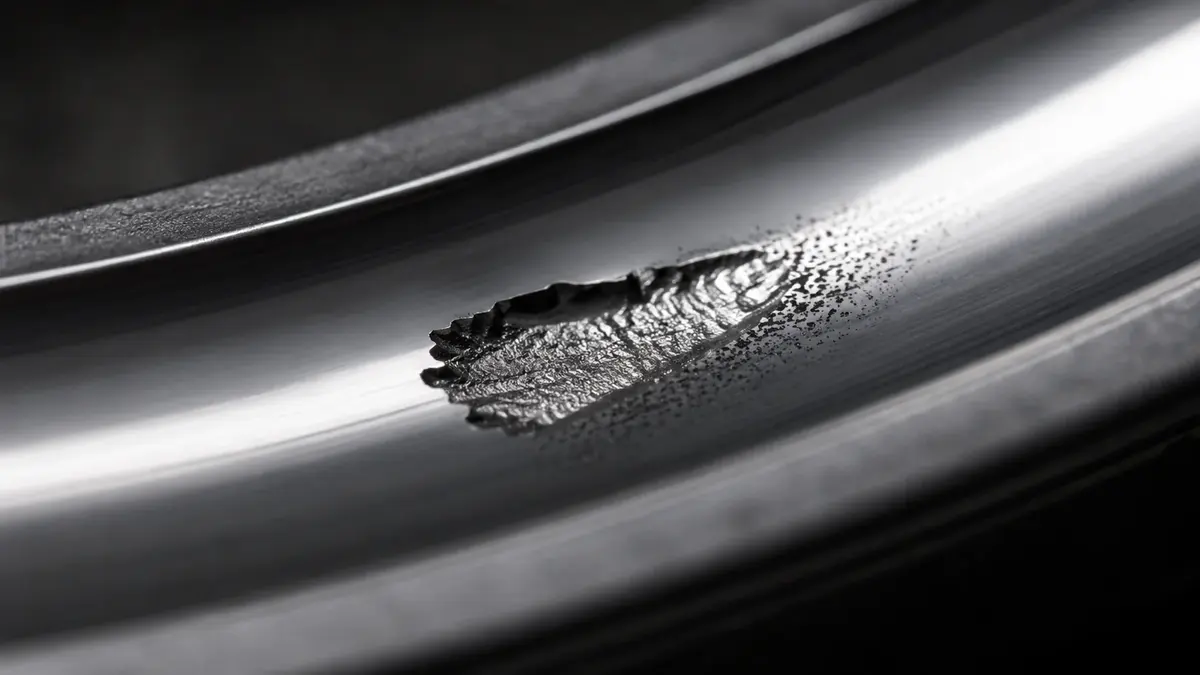
Know when to stop. If the bearing ran to seizure, later damage may have erased the initiating mode. Questions about inclusions, grinding burn or hardness need sectioning, a nital etch and a metallurgical lab, which is outside the visual scope ISO 15243 covers. Checking ring and seat geometry before you scrap the part is worth the time, and how to measure a bearing covers the measurements that matter. Where clearance loss is the suspect, the worked example in bearing internal clearance shows how quickly an interference fit and a thermal gradient consume it.
Lubrication and Contamination: The Preventable Majority
Lubrication and contamination are the two causes a maintenance team controls daily, and in SKF's inspection data they account for 59% of damage causes between them (36% and 23%). Add handling and mounting interface at 8% each and you reach three quarters of everything SKF attributes a cause to.
They also converge on the same failure mode by two different roads. An inadequate film lets asperities touch, which produces surface distress and then surface initiated fatigue (5.1.3). Overrolled particles indent the raceway (5.5.3), and the stress riser at that indentation seeds surface initiated fatigue too. The mode on the report is identical. The fix is not.
Abrasive wear (5.2.2) is the other end state, and at 26% it is the single most common mode in SKF's inspection data. It announces itself as lost finish rather than as a discrete mark.
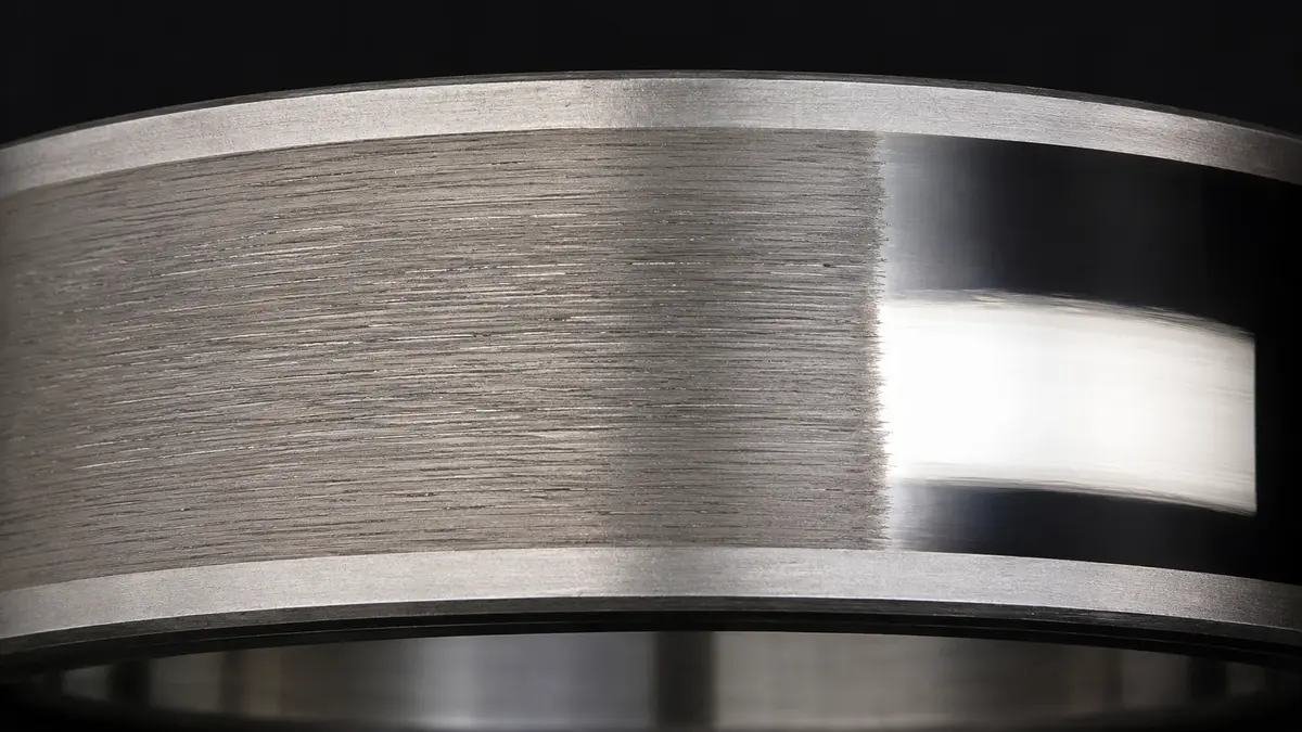
Two multipliers deserve naming because they are easy to miss:
- Water. Water in the lubricant at 100 to 400 ppm measurably reduces rolling-bearing fatigue life. In the 100 to 300 ppm band it can roughly halve life against dry lubricant (Cantley, ASLE Transactions 20(3)). That is a level you cannot see.
- Temperature. Halve the relubrication interval for every 15 °C above 70 °C (NSK). Heat is what quietly turns an adequate schedule into a starvation case.
Neither of these is soft advice sitting outside the standard. ISO 281 modified rating life applies a contamination factor and the viscosity ratio κ, so cleanliness and film thickness are life multipliers inside the calculation itself.
The full treatment of grease against oil, fill quantity, relubrication intervals and the film ratio belongs in the lubrication pillar. For the exclusion side of the problem, sealed vs shielded bearings covers what each closure actually keeps out.
Load, Fit and Clearance: The Failures Specified In
Three specification decisions cause failures before the machine ever runs: too much load for the rating, the wrong fit, and the wrong clearance class for the operating temperature.
Overload is arithmetic
Under ISO 281, L₁₀ scales with (C/P) raised to 3 for ball bearings and 10/3 for roller bearings. Run the exponent and the cost of a load estimate that came in light is not a judgement call:
A 10% load overshoot leaves about 75% of calculated life for a ball bearing and 73% for a roller bearing. At 25% over, life is roughly halved. These percentages are arithmetic on the standard's exponent rather than measured results, which is exactly why they are reliable: no dataset is needed to know that underestimating load is expensive. For how C and C₀ are defined and the full life curve against C/P, see dynamic load vs static load.
True brinelling has a defined threshold
The basic static load rating C₀ is not an arbitrary ceiling. It corresponds to a defined calculated contact stress at the most heavily loaded contact: 4 200 MPa for ball bearings, 4 600 MPa for self-aligning ball bearings, 4 000 MPa for roller bearings. Those stresses produce a total permanent deformation of about 0.0001 of the rolling element diameter (ISO 76:2006, values per SKF).
That is the number behind every instruction not to hammer a bearing, not to press on the wrong ring, and not to drop it. Exceed it at standstill and the dent is designed in.
Fit and clearance
Too loose, and micromovement at the seat produces fretting corrosion (5.3.3.2), creep, and eventually a cracked ring as oxide builds up. Too tight, and hoop stress plus lost radial clearance drives preload, heat, and in the limit forced fracture (5.6.2).
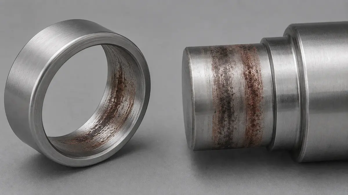
The location is the diagnosis here. This damage sits on the mounting surfaces, not the raceway, so a clean raceway with oxide at the bore points at the fit rather than at anything the bearing was asked to carry.
Clearance is the variable most often judged on the bench and lived with in service. An interference fit consumes part of the initial clearance, and a thermal gradient between inner and outer ring consumes more, so a bearing measured as CN cold can run preloaded hot. The operating clearance calculation is where that gets settled, and the designation suffixes are how you order the result. Where shaft deflection or housing misalignment is in play, misalignment and edge loading covers the load-distribution consequence.
Electrical Erosion: The Mode That Grew With Inverters
Current passing through a bearing erodes the raceway by electrical discharge. The failure has become common wherever variable-frequency drives and inverter-driven traction motors are used, and the two ISO submodes have different signatures and different origins.
Excessive current erosion (5.4.2) heats material to tempering or melting temperatures, leaving discoloured craters. It typically traces to a lightning strike, or to welding on machinery with poor grounding.
Current leakage erosion (5.4.3) is the lower-intensity case. Small adjacent craters develop into a grey washboard pattern, with dull rolling elements and discoloured lubricant. SKF notes it is common in electric motors with stray shaft currents running on a variable-frequency drive.
The diagnostic tell is regularity. Fluting spacing is set by discharge timing and rolling geometry, so it comes out even. Mechanical damage does not distribute itself that neatly.
SKF has studied the electric-vehicle case directly. Real EV motor conditions involve high-frequency AC above 10 kHz, which SKF replicated at 12.5 kHz on a modified ball-on-disc rig under elastohydrodynamic lubrication. The tests produced frosting, pitting and fluting, along with noise-vibration-harshness degradation and lubricant deterioration (SKF Evolution).
That study also produced a result worth knowing, because it runs against instinct. Discharge consistently initiated in the region of minimum film thickness, where electric field strength is highest, and reducing minimum film thickness reduced discharge energy and visible damage. Thicker film raises breakdown voltage but also raises the energy of each discharge. The practical caveat is immediate: push the film too thin and you trade electrical damage for mechanical wear, and SKF is explicit that the optimum band still needs research. Treat lubricant selection here as a balance, not a lever with one direction.
The durable fixes are specification-level. Ground the shaft. Specify current-insulated bearings. Or break the circuit with a hybrid bearing, where silicon nitride rolling elements give high resistance to current passage and so prevent electrical erosion (Schaeffler). For the automotive and EV treatment in depth, see inverter-induced bearing damage in EV traction motors, and for where hybrid ceramics sit among the alternatives, different kinds of bearings.
White Etching Cracks: The Mode Outside the Six
Some premature failures produce extensive subsurface crack networks with a white etching appearance, and they fit neither the standard's six appearance classes nor a straightforward reading of rating life. Bearings sometimes fail at 5% to 10% of calculated rating life in specific applications, and a characteristic feature of many of those failures is white etching cracks (SKF Evolution).
Wind turbine gearboxes are the flagship case. Actual gearbox service life often falls well below the desired 20 years. White structure flaking has been reported in as little as 6 to 24 months, forming through axial cracks and white etching cracks (Evans, Materials Science and Technology). The same damage appears in automotive drivelines, alternators, paper mills and marine propulsion.
What the industry disagrees about is the mechanism. Evans notes the drivers and mechanisms remain "highly contested" after two decades of observation. Writing in 2018, SKF described roughly 15 years of debate and "a lack of consensus about the root cause and failure mechanisms among the main players." Proposed contributors include non-metallic inclusions, severe sliding, hydrogen entry, transient loads and electrical stray currents.
SKF's own published position is the citable anchor, and it is specific. WECs "occur at the end of the failure chain, and are a natural consequence of crack networks in prematurely failed bearings." That makes them a symptom rather than the root cause of fatigue failure. SKF frames premature failure through the weakest link, where local stress exceeds local strength. It also notes that inclusions "are a natural part of all bearing steels." The conclusion is blunt: "A single root cause does not exist, and each failure case needs to be reviewed in the light of the corresponding operating conditions."
Why this matters at the bench: the six-mode chart will not name this one. If a bearing fails at a small fraction of design life and the raceway shows axial cracking rather than a single classic spall, the investigation belongs in a metallurgical lab.
It also sharpens what "meets the standard" is worth. A load rating calculated to ISO 281 assumes the material's weakest link has not been significantly weakened. That assumption is a statement about steel cleanliness and heat treatment, not about a logo. Ask for the evidence: inclusion ratings, hardness and case depth, and the heat-treatment route. Rolling mill bearing materials covers what those numbers mean, and bearing manufacturers covers who publishes failure-analysis references worth reading.
Catching It Early, and Specifying So It Does Not Repeat
Bearing degradation is detectable long before it is audible, and each detection technique buys a different amount of warning.
Condition-monitoring practice describes a four-stage progression. Stage 1 appears only in the ultrasonic range, from roughly 20 kHz, with more than 10% to 20% of L₁₀ life remaining. Seeing it needs high-frequency demodulation, spike energy or shock pulse. Stage 2 excites bearing natural frequencies, commonly cited in the 2 to 6 kHz range, with less than 5% to 10% remaining. Stage 3 brings the discrete defect frequencies into the spectrum: BPFO, BPFI, BSF and cage frequency, with harmonics and running-speed sidebands. Less than 1% to 5% of life is left. Stage 4 replaces those discrete frequencies with a broadband noise floor as clearances open up, and catastrophic failure can happen at any time (CBM Connect).
Treat those figures as condition-monitoring practice rather than standard values. They come from reliability practitioners and vendors, not from an ISO document. The sources also disagree on detail. Ludeca's four-stage reference puts bearing natural frequencies at 30 000 to 90 000 CPM, a different band from the 2 to 6 kHz above (Ludeca).
The decision rule survives the disagreement. Once stage 3 is confirmed, plan the shutdown and replace at the earliest opportunity, increasing check frequency if the machine cannot stop. Stage 4 is where collateral damage to shafts, housings and couplings gets added to the bill.
Closing the loop from mode to specification
Diagnosis is only worth the effort if it changes a decision. Each mode has a control, and most of them are decided long before maintenance sees the machine.
| Failure mode (ISO clause) | Control that closes it | Decided at |
|---|---|---|
| Abrasive wear (5.2.2) | Seal selection, filtration, exclusion at install | Design and install |
| Adhesive wear (5.2.3) | Minimum load check, clearance and preload | Design |
| Moisture corrosion (5.3.2) | Closure rating, drainage, lubricant with water tolerance | Design and maintain |
| Fretting corrosion (5.3.3.2) | Fit class matched to load and which ring rotates | Design |
| False brinelling (5.3.3.3) | Transport restraint, rings packed separately, preload | Storage and transport |
| Electrical erosion (5.4.2, 5.4.3) | Shaft grounding, insulated or hybrid bearings | Design |
| Overload deformation (5.5.2) | Static safety factor s₀, press on the fitted ring only | Design and install |
| Particle indentation (5.5.3) | Cleanliness at assembly, filtration | Install and maintain |
| Surface initiated fatigue (5.1.3) | Viscosity at real operating temperature, κ and film ratio | Design and maintain |
| Forced fracture (5.6.2) | Interference control, drive-up measurement on tapered bores | Install |
The sourcing angle follows from the same table, and it is a verification question rather than a brand question. In SKF's inspection data, fatigue accounts for 2% of damage causes. Ask any supplier four things:
- Which standard and revision produced the load rating.
- What clearance class ships as standard.
- What the closure is rated to exclude.
- What evidence exists for steel cleanliness and heat treatment.
Those four answers predict failure behaviour far better than the country on the box does. How to source Chinese bearings overseas covers how to get them in writing.
ANDE's rolling mill bearings and deep groove ball bearings ship with the clearance class and rating basis stated up front. If you have a failed bearing on the bench, the engineering desk will review a photo set and the duty case with you. Contact engineering.
Frequently Asked Questions
What causes most bearing failures?
In SKF's own inspection dataset, the largest causes are lubrication (36%) and contamination (23%). Application follows at 18%, then mounting interface (8%), handling (8%), electrical (5%) and fatigue (2%) (SKF Evolution). Note the population: these are bearings sent to SKF for inspection, not all bearings in service. SKF also publishes shorter rules of thumb, and they differ between publications, so quote the document rather than the number alone.
What percentage of bearings fail?
About 0.5%. SKF reports that roughly 90% of bearings outlive the equipment they are installed in. About 9.5% are replaced preventively before failure, and approximately 0.5% are replaced because they were damaged or failed (SKF, PUB 14219/3). Schaeffler/FAG independently states that only about 0.35% of all rolling bearings do not reach expected life.
What are the failure modes in ISO 15243?
Six, classified by appearance: rolling contact fatigue (clause 5.1), wear (5.2), corrosion (5.3), electrical erosion (5.4), plastic deformation (5.5), and cracking and fracture (5.6). Those six contain 14 submodes. Some sources renumber these as "Category 1" through "Category 6" or similar; the clause numbers above are the ones in ISO 15243:2017.
What is the difference between true and false brinelling?
True brinelling is overload deformation (5.5.2): permanent indentation from static overload or impact. Material is displaced rather than removed, so the original ground finish is usually still readable inside the dent.
False brinelling is a corrosion submode (5.3.3.3): wear at rolling-element spacing caused by vibration or small oscillation while the bearing is stationary. It removes the original manufacturing finish and often leaves red or blackish oxidation.
One is a load and mounting problem. The other is a vibration, transport and storage problem. NSK's countermeasures include securing the shaft and housing during transport and packing the rings separately.
Can you diagnose a bearing failure just by looking at it?
Usually you can name the failure mode, which is what ISO 15243 is designed for. The root cause needs the operating context too: load, speed, fit, seal condition, lubricant and drive type. SKF puts it directly, saying it is "perhaps more important" to understand what caused the failure than to name the mode. If the bearing ran to seizure, or the question is subsurface, a metallurgical examination is required.
Conclusion
Bearings mostly outlive their machines, so a failure is a signal about the application rather than a verdict on the part. A few things carry most of the diagnostic value:
- Attach a denominator to every percentage. 0.5% counts all bearings in service. 36% counts causes in bearings that were inspected. 26% counts modes in those same inspections. Quoting one as if it were another is the most common error on this topic.
- The six ISO 15243 modes are 5.1 through 5.6, and they classify appearance, not cause. Naming the mode is step one, not the answer.
- Appearance gives the mode, context gives the cause. The ground finish inside a mark separates true from false brinelling. Regular fluting spacing separates current from wear.
- The preventable majority is lubrication, contamination, handling and fit, which is about three quarters of what SKF attributes a cause to. Classic fatigue is 2%.
- Some premature failures sit outside the chart. White etching cracks are, on SKF's published position, a consequence rather than a root cause, and no single root cause has been agreed.
The practical close is a specification habit. Ask which standard produced the rating, what clearance class ships, what the closure excludes, and what evidence exists for steel cleanliness and heat treatment. Then check the fit, the film and the drive before the replacement goes in. For the single largest controllable cause, continue with the bearing lubrication guide, or send the photo set and duty case to ANDE's engineering desk through contact.
About the Author
Jeff Li writes on bearing engineering and global sourcing for ANDE Bearing. He works directly with OEM and aftermarket buyers in automotive, heavy industry, and renewable energy. Connect on LinkedIn.