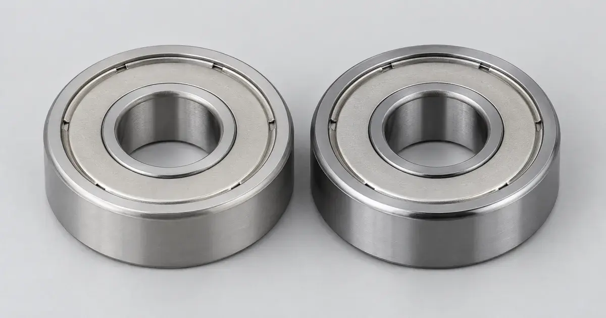
A 6208 deep groove ball bearing carrying 2,500 N of radial load calculates to roughly 39,000 hours. Add 1,000 N of thrust and the same bearing calculates to about 21,000 hours. The bearing did not change, the speed did not change, and the resultant force rose by under 8%. What changed was the direction of part of the load, and the catalogue punished it by nearly half the service life (NSK, retrieved 2026-08-24).
That is the whole reason load direction is worth a page of its own. Radial load acts perpendicular to the shaft axis, axial load acts along it, and a bearing catalogue publishes a single rating that neither one matches directly. This guide covers three things. The ratio that decides whether thrust counts at all. The ISO 281 arithmetic that converts two force components into the one number the rating is compared against. And the hard axial ceiling for each bearing type, including the several types where that ceiling is zero.
Key Takeaways
- Radial load acts perpendicular to the shaft axis; axial load, also called thrust, acts along it. Almost no real application is purely one, so the load case that governs selection is the combined one.
- A catalogue rates one number, so two force components must be reduced to one. Under ISO 281 that number is the equivalent dynamic load, P = X Fᵣ + Y Fₐ.
- Below a bearing-specific threshold e, axial load is free. Above it the axial term enters the life calculation, and it bites hard because L₁₀ scales with (C/P)³ for ball bearings.
- Every type has a hard axial ceiling. A standard single row deep groove ball bearing accepts pure axial load only up to Fₐ ≤ 0.5 C₀, and only 0.25 C₀ in small or light series. A non-locating NU cylindrical roller bearing accepts none at all.
- Angular contact and tapered roller bearings generate axial load internally, from radial load alone. That induced force belongs in the calculation even when nothing external pushes on the shaft.
Axial and Radial Load, Defined Once
Radial load acts perpendicular to the shaft axis. Axial load acts parallel to it, and thrust is simply the common name for axial load. ISO 5593 is where the vocabulary is fixed, which matters more than it sounds: vendor glossaries drift, and a term that appears on a drawing needs a standard behind it.
That is the entire distinction, and it is worth stating plainly because it is where most published treatments of this question stop. Knowing which way the arrow points does not tell you what bearing to buy. If you need the map before the arithmetic, the survey of different kinds of bearings sorts the types by what each one can carry.
There is also a third component that gets left out of the axial-versus-radial framing entirely. A moment load appears whenever the resultant force does not pass through the bearing centre, and it loads one side of the raceway while unloading the other. A single narrow bearing cannot support it. When your load case includes a real moment, the answer is a different arrangement rather than a factor in a formula. Use a bearing pair at a spread, a double row bearing, or a four-point contact design. Reaching for X and Y factors on a moment-loaded shaft produces an answer that is arithmetically clean and mechanically wrong.
The Real Load Case Is Combined
Pure radial and pure axial are textbook cases. Production machinery delivers both at once, and the ratio between them is what actually selects the bearing.
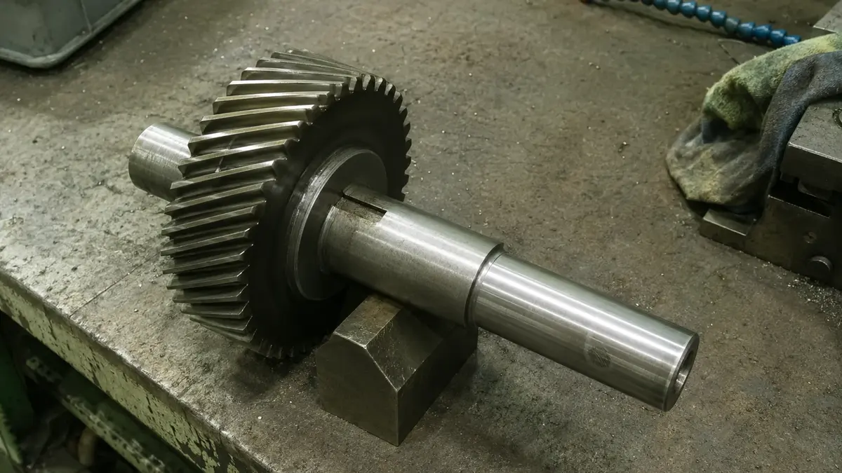
The axial component usually arrives from the drive rather than from anything obviously thrust-like. Helical gear teeth generate it by tooth geometry. Bevel gears and worm drives generate it as a major component, and on a worm it is usually the dominant one. Belt pull contributes a circumferential load whose magnitude depends on transmitted torque. An angular contact pair generates it internally, which the section below covers on its own. Thermal growth of the shaft against a second locating bearing generates it with no external force involved at all.
Two multipliers convert a theoretical drive force into a bearing load, and both come from SKF's own selection guidance (retrieved 2026-08-24):
| Source | Condition | Factor |
|---|---|---|
| Gears | Pitch and form errors below 0.02 mm | 1.05 to 1.1 |
| Gears | Pitch and form errors 0.02 to 0.1 mm | 1.1 to 1.3 |
| Belts | Toothed belts | 1.1 to 1.3 |
Gears held to high accuracy have negligible additional forces. Lower precision gears do not, and the factor is the honest way to carry that into the load case.
One boundary is worth stating before any arithmetic starts. Every catalogue method here treats the shaft as a statically determined beam resting on rigid, moment-free supports. Elastic deformation of the bearing, the housing and the machine frame is ignored, and so are the moments produced by shaft deflection. Those simplifications are what make the calculation possible by hand, and they are also the reason a flexible shaft in a compliant housing eventually needs system software rather than a formula. Knowing where the method stops is part of using it correctly.
The Threshold That Decides Whether Thrust Counts
For a single row radial bearing, axial load changes the life calculation only once the ratio Fₐ/Fᵣ exceeds a limiting value e. Below e, the equivalent load is simply P = Fᵣ and the thrust costs nothing. Above e, the axial term enters and starts to dominate.
The trap is treating e as a constant. It is published per bearing in the product table, and for deep groove ball bearings it moves with the ratio f₀Fₐ/C₀ᵣ. It therefore depends on the axial load you are testing against it. You cannot look up one number for "ball bearings" and reuse it.
Double row bearings do not get the free-thrust allowance at all. For a double row bearing, even light axial loads affect the equivalent load and have to be counted, where a single row bearing below e ignores them entirely. That is a real selection lever and it points the opposite way to intuition: doubling the rows buys capacity, not tolerance for unmeasured thrust.
Converting Radial and Axial Load Into One Number
ISO 281 defines the equivalent dynamic load P as the hypothetical load that would have the same effect on bearing life as the actual combined load, and calculates it as:
P = _X F_ᵣ + _Y F_ₐ
| Symbol | Meaning |
|---|---|
| P | equivalent dynamic bearing load [kN] |
| Fᵣ | actual radial bearing load [kN] |
| Fₐ | actual axial bearing load [kN] |
| X | radial load factor for the bearing |
| Y | axial load factor for the bearing |
Worked through on the 6208 from the opening, using NSK's own catalogue example. The bearing's ratings are Cᵣ = 32,000 N and C₀ᵣ = 17,900 N, with f₀ = 14.0. The load case is Fᵣ = 2,500 N and Fₐ = 1,000 N.
- Find the threshold. f₀Fₐ/C₀ᵣ = 14.0 × 1,000 / 17,900 = 0.782, which gives e ≈ 0.26.
- Test the ratio. Fₐ/Fᵣ = 1,000 / 2,500 = 0.4, which exceeds e. The axial term applies.
- Read the factors. X = 0.56, and Y = 1.67 by linear interpolation in the catalogue table.
- Compute. P = 0.56 × 2,500 + 1.67 × 1,000 = 3,070 N.
Two things in that chart deserve a second look. The radial factor X = 0.56 discounts the measured radial load, from 2,500 N down to a 1,400 N contribution. The axial factor Y = 1.67 amplifies the measured axial load, from 1,000 N up to a 1,670 N contribution. So the axial term ends up larger than the radial term even though the thrust is only 40% of the radial force.
The cost in life follows from the exponent. L₁₀ scales with (C/P)³ for ball bearings, so raising P from 2,500 N to 3,070 N multiplies calculated life by (2,500/3,070)³ = 0.54. NSK's own life factors for the same case move from 4.26 to 3.47, which is the same 0.54 by a different route, and lands as roughly 39,000 hours falling to about 21,000. Around 46% of the calculated life is gone. This is the same sensitivity that makes a 10% load overshoot cost about a quarter of calculated life, covered in more detail in the guide to bearing failure modes.
At this operating point, a kilonewton of thrust is less damaging than a kilonewton of extra radial load. Adding 1,000 N axially gives P = 3,070 N. Adding the same 1,000 N radially instead gives P = 3,500 N, because a purely radial load is compared against the rating directly with no 0.56 discount. The popular framing of thrust as the uniquely dangerous direction is not what the arithmetic says. What makes axial load dangerous is not the factor, it is the ceiling in the next section, and the fact that Y keeps climbing as the ratio grows while X stays put.
One caution on that comparison: it holds at the verified operating point and does not generalise into a curve. Y is not a constant either, since it falls as f₀Fₐ/C₀ᵣ rises, so the crossover moves with the load case. Read the factors for the actual bearing and the actual loads rather than reusing a pair.
For the ratings C and C₀ themselves, and how the L₁₀ formula and the s₀ safety factor are built on them, see dynamic load vs static load in bearings.
The Static Side of the Same Question
The direction split appears again in the static check, with different coefficients and under a different standard. For a single row deep groove ball bearing, ISO 76 gives the equivalent static load as P₀ = 0.6 Fᵣ + 0.5 Fₐ. One floor condition comes with it: if P₀ comes out below Fᵣ, then P₀ = Fᵣ.
Run the same 6208 case through it. P₀ = 0.6 × 2,500 + 0.5 × 1,000 = 2,000 N, which is less than the 2,500 N radial load, so the floor takes over and P₀ = 2,500 N. The thrust drops out of the static check entirely. That is not an error in the method, it is the method refusing to let a weighted average understate a load the bearing genuinely carries.
The static coefficients also punish arrangement in a way the dynamic ones do not. For a matched pair mounted back-to-back or face-to-face, the same source gives P₀ = Fᵣ + 1.7 Fₐ. The axial coefficient more than triples, from 0.5 to 1.7.
The Axial Ceiling, Type by Type
Every bearing type has a hard limit on how much axial load it may carry, and for several types that limit is zero. This is separate from the equivalent-load arithmetic: a load case can pass the life calculation and still be inadmissible.
| Bearing type | Axial capacity | Equivalent dynamic load, above e |
|---|---|---|
| Deep groove ball, single row | Pure axial Fₐ ≤ 0.5 C₀ | P = X Fᵣ + Y Fₐ |
| Deep groove ball, d ≤ 12 mm or diameter series 8, 9, 0, 1 | Pure axial Fₐ ≤ 0.25 C₀ | P = X Fᵣ + Y Fₐ |
| Deep groove ball, stainless | Pure axial Fₐ ≤ 0.25 C₀ | P = X Fᵣ + Y Fₐ |
| Deep groove ball, with filling slots | Fₐ ≤ 0.6 Fᵣ | P = Fᵣ + Fₐ when Fₐ/Fᵣ ≤ 0.6 |
| Deep groove ball, double row | Pure axial Fₐ ≤ 0.5 C₀ | P = X Fᵣ + Y Fₐ, axial always counts |
| Angular contact ball, single row | By contact angle and arrangement | P = X Fᵣ + Y₂ Fₐ |
| Cylindrical roller, non-locating | None | P = Fᵣ |
| Cylindrical roller, flanged both rings, locating | Fₐ ≤ 0.5 Fᵣ | P = 0.92 Fᵣ + Y Fₐ |
| Tapered roller, single row | By contact angle, in opposed pairs | P = 0.4 Fᵣ + Y Fₐ |
| Spherical roller | Accepts purely axial load | P = 0.67 Fᵣ + Y₂ Fₐ |
| Thrust ball | Axial only | P = Fₐ |
Sources for the table are the per-type SKF product data, retrieved 2026-08-24.
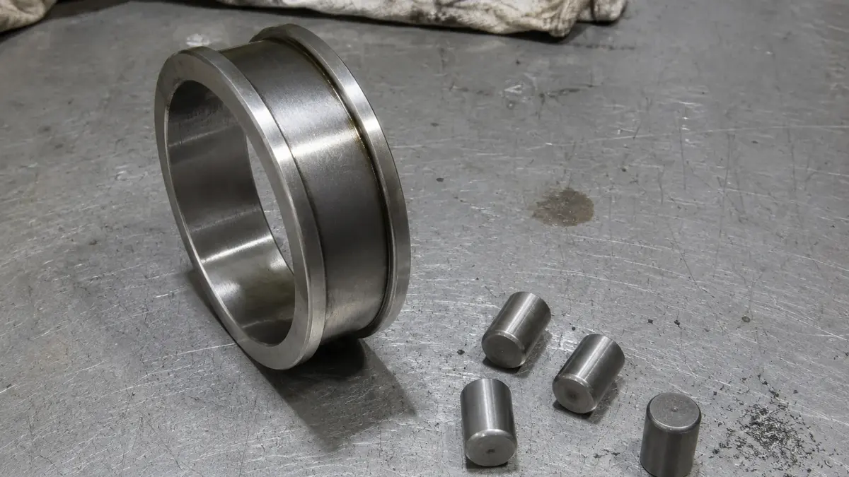
Several rows deserve calling out. A non-locating cylindrical roller bearing carries no thrust at all, and its static equivalent load is P₀ = Fᵣ with no axial term to add. Flange the bearing on both rings, use it as a locating bearing, and it takes Fₐ up to 0.5 Fᵣ. That is a different part, not a different calculation on the same part. A thrust ball bearing has no radial term in either the dynamic or the static model, because radial load is not what it is for. Once the thrust is the whole load case rather than a component of it, the selection moves to purpose-built thrust bearings and stops being a question about direction ratios.
Spherical roller bearings accommodate axial load and even purely axial load, which makes them the outlier in the table. Their ceiling is mounting-dependent rather than geometry-dependent: correctly mounted on an adapter sleeve on a plain shaft with no fixed abutment, the permissible axial load drops to Fₐₚ = 0.003 B d. The bearing did not get weaker, the friction grip holding it on the shaft became the limit.
The Axial Ceiling Is Not the Static Rating Ceiling
Here is the part that gets missed, and it is the reason a load case can clear every calculation above and still destroy the bearing.
The permissible axial load on a deep groove ball bearing is the load at which the contact ellipse rides over the shoulder of the raceway groove. As the axial load grows, the contact angle changes, and the elliptical contact patch migrates up the groove flank until part of it runs off the edge. NSK states directly that this is a different limit from the P₀ value derived from C₀ and the static axial factor Y₀. It also states the consequence: the contact ellipse may ride over the shoulder even when the axial load is below the P₀ limit (NSK catalogue E1103, retrieved 2026-08-24).
A static check that passes does not prove the axial load is admissible. The static rating governs permanent deformation at the contact. The axial ceiling governs whether the contact stays on the raceway at all. They are different failure mechanisms with different limits, and the geometric one can trigger first.
Applied to the running example: the 6208 is in diameter series 2 with a 40 mm bore, so neither exception applies. Its pure axial ceiling is 0.5 × 17,900 = 8,950 N. The 1,000 N of thrust in the load case is comfortably inside it. Move the same 40 mm bore into diameter series 0 and the ceiling drops to a quarter of C₀. That is the kind of substitution that looks dimensionally identical on a drawing and is not equivalent in service. The same trap in a different form shows up when cross-referencing a bearing number across manufacturers.
The Axial Load Nobody Applied
A single row angular contact or tapered roller bearing transmits radial load from one raceway to the other at an angle to the bearing axis. That oblique load path induces an internal axial force with no external thrust present. It is a consequence of the contact angle, not of anything the machine is doing. This is the reason these bearings are mounted in opposed pairs rather than singly: the pair gives the induced force somewhere to react.
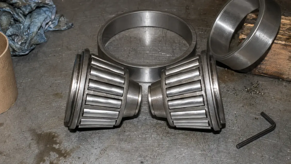
The practical consequence is that the induced component has to be carried into the equivalent-load calculation for adjusted arrangements built from two single bearings or from tandem pairs. Leave it out and the calculation is not conservative, it is simply wrong, because the bearing is carrying thrust that never appeared in the load case.
The catalogue equations for those arrangements come with conditions that are easy to miss and easy to violate on a real drawing. They are valid only when both bearings have identical contact angles and are adjusted against each other to practically zero clearance, without preload. Mount the pair with clearance, mount it with preload, or mix contact angles across the pair, and the equations no longer describe the arrangement. At that point the problem belongs in bearing arrangement software rather than in a spreadsheet.
There is a related arrangement error that produces axial load from nothing at all: two locating bearings on one shaft. Both ends are axially fixed and the shaft grows with temperature. The growth has nowhere to go except into the bearings, as axial load that appears in no load case and on no drawing. One locating bearing and one non-locating bearing is the arrangement that avoids it, which is exactly why the non-locating cylindrical roller bearing in the table above carries no thrust by design.
For contact angles and the DB, DF and DT arrangement codes in detail, see the guide to angular contact ball bearings. For the choice between the two roller types in a locating and non-locating pair, see tapered vs cylindrical roller bearings.
Too Little Load Is Also a Load Case
A bearing that is too lightly loaded fails by skidding and smearing rather than by fatigue. The rolling elements need enough load to roll rather than slide. Below that point the failure mechanism changes entirely, which is why every bearing has a minimum load as well as a maximum.
The general rule from SKF (retrieved 2026-08-24) is 0.01 C for ball bearings and 0.02 C for roller bearings. For the 6208, that is 0.01 × 32,000 = 320 N, and the 2,500 N radial load clears it by a wide margin.
Minimum load is specified per direction for the types that need it. A single row tapered roller bearing carries either Fᵣₘ = 0.017 C or Fₐₘ = 0.009 C/Y, depending on which direction is doing the loading. A spherical roller bearing wants Pₘ = 0.01 C₀, dropping to 0.003 C₀ when it is oil lubricated below 0.3 of the reference speed.
The requirement bites hardest under rapid acceleration, rapid starts and stops, and at speeds above 50% of the limiting speed listed in the product table. Those are the conditions where a rolling element has the most opportunity to lose traction. When the minimum cannot be met, the remedies in order are a smaller dimension series, special lubrication or a running-in procedure, a coated bearing, or applied preload. Preload is the most common answer, and it interacts directly with the clearance group you order, covered in the guide to bearing internal clearance.
A Six-Step Load-Direction Check
The full check is six steps. The two that get skipped in practice are induced load and the axial ceiling, and skipping either one produces a calculation that looks complete and is not.
- Resolve the external forces into Fᵣ and Fₐ at each bearing position, applying the gear or belt load factor from the drive.
- Add the induced axial force if the bearing is angular contact or tapered roller, before anything else is computed.
- Look up e for the specific bearing, then compute Fₐ/Fᵣ and compare.
- Compute P. Above e, P = X Fᵣ + Y Fₐ with that bearing's factors. Below e, P = Fᵣ, but only for a single row bearing.
- Check the ceiling and the static case. Test the axial load against the permissible ceiling for the type, and separately test P₀ against C₀ for the peak or stationary condition.
- Check the minimum load at the low end of the duty cycle, not just the high end.
Run end to end, the 6208 case produces:
- Step 1. Fᵣ = 2,500 N and Fₐ = 1,000 N.
- Step 2. No induced component, since it is a deep groove ball bearing.
- Step 3. e ≈ 0.26 against a ratio of 0.4, so the axial term applies.
- Step 4. P = 3,070 N, against Cᵣ = 32,000 N.
- Step 5. Axial load 1,000 N against a ceiling of 8,950 N. P₀ = 2,500 N against C₀ᵣ = 17,900 N, a static safety factor of 7.2.
- Step 6. A minimum load requirement of 320 N, which the application clears.
Every one of those numbers traces to a published standard or a product table.
That traceability is the point. A bearing that satisfies all six steps is defensible to a quality department regardless of who manufactured it. The argument rests on ISO 281, ISO 76, and load ratings the maker publishes and can be audited against. Specify the numbers and the standards, and the origin question answers itself.
Frequently Asked Questions
Can a ball bearing take axial load?
Yes. A standard single row deep groove ball bearing accepts pure axial load up to Fₐ ≤ 0.5 C₀, its basic static load rating. Two categories are held to half that, at 0.25 C₀: bearings with a bore of 12 mm or under, and bearings in diameter series 8, 9, 0 and 1. Stainless steel deep groove ball bearings are also limited to 0.25 C₀. Exceeding the ceiling can reduce service life considerably, and the governing mechanism is the contact ellipse riding over the raceway shoulder rather than static overload.
What is the difference between axial and radial load?
Radial load acts perpendicular to the shaft axis, and axial load acts along it. Axial load is also called thrust. ISO 5593 fixes the vocabulary. A third case, moment load, arises when the resultant force does not pass through the bearing centre. It needs a bearing pair or a double row design rather than a load factor.
Which bearings handle combined axial and radial load best?
Tapered roller, angular contact ball, and spherical roller bearings, and each carries the combined case differently. A single row tapered roller bearing uses P = 0.4 Fᵣ + Y Fₐ above the threshold. A single row angular contact ball bearing uses P = X Fᵣ + Y₂ Fₐ. A spherical roller bearing uses P = 0.67 Fᵣ + Y₂ Fₐ and will accept a purely axial load, which the other two will not in a single mounting. The tapered and angular contact types both need opposed pairs because they induce axial load internally.
Can a cylindrical roller bearing take thrust?
Only in the flanged, locating configuration. A cylindrical roller bearing flanged on both the inner and outer rings supports axial load up to Fₐ ≤ 0.5 Fᵣ alongside its radial load. Above the threshold it uses P = 0.92 Fᵣ + Y Fₐ. Used as a non-locating bearing, it carries no axial load at all. Its equivalent dynamic load is simply P = Fᵣ, and its equivalent static load is P₀ = Fᵣ with no axial term. That inability to take thrust is a design feature, since it is what lets the shaft grow thermally without loading the bearing.
What happens if you underestimate the axial load?
Two separate things, on two separate mechanisms. The calculated life falls with the cube of the increase in equivalent load for a ball bearing, so a load case that understates thrust overstates life. Independently, the contact ellipse can ride over the raceway shoulder, and that can happen even when the axial load is below the P₀ static limit. A passing static check is not proof of admissibility. The resulting damage is classified under ISO 15243, and the patterns are covered in the guide to bearing failure.
Conclusion
Load direction is a calculation, not a category. Three things carry most of the weight:
- The ratio decides. Below the bearing's own threshold e, axial load does not enter the life calculation. Above it, P = X Fᵣ + Y Fₐ, and the axial term can exceed the radial term while the thrust is still a minority of the total force.
- The conversion is standardised. ISO 281 for the dynamic case and ISO 76 for the static one, with factors published per bearing rather than per type. Read them for the actual part.
- The ceiling is per type, and separate from the ratings. 0.5 C₀ for a standard deep groove ball bearing, 0.25 C₀ for small and light series, 0.5 Fᵣ for a flanged locating cylindrical roller bearing, and zero for the non-locating one. The geometric limit can be reached before the static limit.
If you have a load case with both components, send the application data to ANDE Bearing's engineering team: radial load, axial load, speed, and the envelope you have to fit. We will return a bearing recommendation with the ISO 281 calculation attached, so the selection can be checked rather than taken on trust. You can also start from the type you already know you need, in deep groove ball bearings, tapered roller bearings, or cylindrical roller bearings.
About the Author
Jeff Li writes on bearing engineering and global sourcing for ANDE Bearing. He works directly with OEM and aftermarket buyers in automotive, heavy industry, and renewable energy. Connect on LinkedIn.