
圧延機ロールネックに不適切な軸受構造を選択することは、単に整備間隔を短縮するだけでは済みません。生産ライン全体を停止させてしまいます。4列円すいころ軸受と4列円筒ころ軸受は、それぞれ根本的に異なる工学的課題を解決するものです。ミルスタンドに不適切なタイプを充てることは、調達担当や保全チームが犯しうる最も高コストなミスの一つです。熱間圧延機の計画外停止は、わずか1時間で長年にわたる軸受コスト削減の成果を帳消しにしてしまいます。したがってこの選定は、工学的判断であると同時に財務的判断でもあります。
本ガイドでは、構造的な差異を分解し、最も重要な変数にわたって性能を比較します。目的は、お客様の特定のミルスタンドに適した軸受を選ぶための実践的なフレームワークを提供することです。
重要ポイント
- ラジアル荷重とアキシャル荷重の複合荷重が支配的な粗圧延機および中間圧延機には、4列円すいころ軸受を使用してください。
- 速度と純粋なラジアル容量がアキシャル統合性よりも重要な仕上圧延機には、4列円筒ころ軸受を使用してください。
- スラブは2,300〜2,400°F(約1,260〜1,316°C)で熱間圧延機に投入されます(AIST、2020年)。チョックはその輻射熱環境の中に置かれます。
- どちらの構造も普遍的に優れているわけではありません。荷重プロファイル、速度域、チョック設計が整合してから選定を確定してください。
ロールネック軸受を規定する稼働条件とは何ですか?
ロールネック軸受は、過酷な熱・荷重環境の中で稼働します。スラブは再加熱炉から熱間圧延機に2,300〜2,400°F(約1,260〜1,316°C)で投入され、仕上ストリップは1,000〜1,300°F(約538〜704°C)で巻き取られます(AIST、2020年)。その熱は、軸受が収まるチョック内へと輻射します。ミルスケール、水、プロセス残渣があらゆる露出面を攻撃します。各軸受は数百トン単位のラジアル荷重を吸収し、キャンペーン全体を通して1時間に数千回繰り返し荷重を受けます。
そのような環境において、ロールネック軸受は生産スタンドの要となります。軸受が故障すれば、スタンドは停止します。軸受構造の選定は、ユニットコストではなく、各スタンド固有の荷重特性によって決定されるべきです。
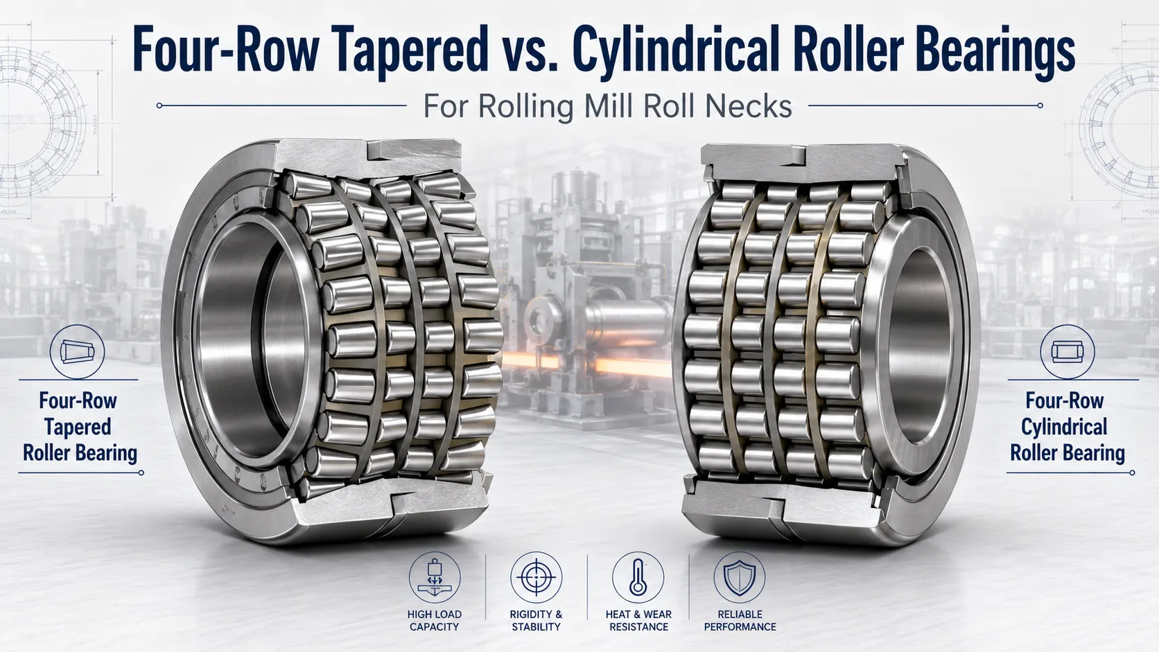
4列円すいころ軸受は、鋼、アルミニウム、銅、その他の金属圧延環境において、複合荷重を受けるポジションでの実績が十分に確立されています。4列円筒ころ軸受はほぼ金属産業に専用で、仕上圧延機ポジションで重ラジアル荷重を支えます。どの構造がどこに適合するかを理解するための出発点は、各スタンドの荷重プロファイルです。
圧延機にはどのような軸受が使用されるのですか? ロールネック用途で支配的な2タイプは、4列円すいころ軸受と4列円筒ころ軸受です。円すい設計はラジアルとアキシャルの複合荷重を単一アセンブリ内で処理するため、粗圧延機および中間圧延機の標準となっています。円筒設計は純粋なラジアル容量と速度に特化しているため、仕上圧延機での第一選択となります。ほとんどの圧延ラインは、スタンド位置に応じて両タイプを併用しています。
4列円すいころ軸受はどのような場合に指定すべきですか?
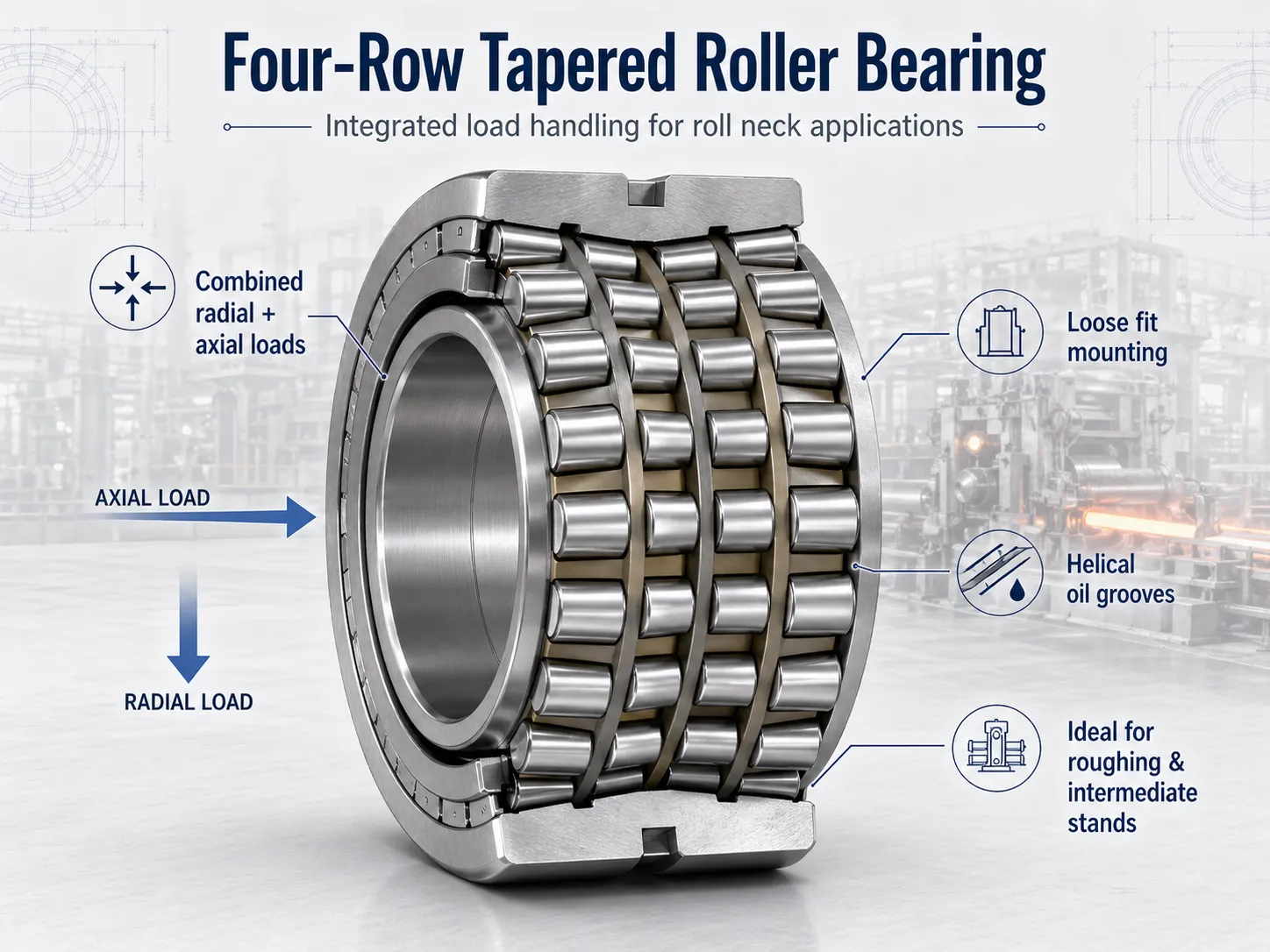
4列円すいころ軸受の決定的な優位性は、単一の統合アセンブリ内でラジアル荷重とアキシャル荷重を同時に支持できる点にあります。粗圧延機および中間圧延機では、方向転換、ビレット進入力、ロールシフトが複雑な多方向荷重パターンを生み出します。円すい設計は、これらすべてを補助スラストコンポーネントなしで処理します。
自己完結型の荷重処理
アキシャル容量が円すい形状そのものに組み込まれているため、エンジニアはロールネックアセンブリに専用のスラストカラーや補助アキシャル軸受セットを設計する必要がありません。コンポーネント数が少ないということは、故障点が少なく、寸法管理がより厳密で、ハウジングボアがよりクリーンであることを意味します。 システムの複雑さを増すことなく最も幅広い荷重処理能力を提供する軸受は、一貫して円すい設計です。これこそが、圧延ラインの中で最も荷重の重いスタンド位置において、円すい設計が依然としてデフォルトの選択肢である理由です。
迅速なロール交換のためのすきまばめ取付
4列円すいころ軸受は通常、ロールネックに対して意図的なすきまばめで取り付けられます。固定機械であれば締まりばめが有効に機能しますが、1シフトで複数回ロールを交換する必要がある場合には負担となります。すきまばめ取付であれば、保全担当者は専用の引き抜き工具なしでロールアセンブリを迅速に取り外し・再取付できます。各交換サイクルを通じて、軸受ボアとロールネック表面の双方を保護します。
らせん油溝:なぜクリープ抑制が重要なのですか?
ロールネック軸受の仕様における重要な設計上のディテールは、軸受ボアに加工されたらせん油溝です。 私たちが取引する圧延機のお客様において、買い手が価格を追求する際に最も頻繁に妥協されている仕様が、まさにこのらせん油溝の形状です。この溝は内輪とシャフトの間で潤滑剤を循環させ続け、ロールネッククリープと呼ばれる微小すべり現象を能動的に防止します。放置すれば、クリープはフレッチング摩耗を発生させ、ボアとシャフトの双方を劣化させます。これは高コストな故障モードです。厳密な寸法公差で製造された4列円すいころ軸受では、らせん油溝の設計は標準仕様です。低品質な代替品でこれが省かれていることは、定量化可能なリスクを意味します。
円すい設計が限界に達する領域
主な制約は速度です。円すい形状に固有のつば-ころ接触界面は、高い回転速度において追加の発熱を生じます。これは高スループットの仕上用途における実質的な制約となります。また、円すい軸受は取付時に精密な予圧設定を要するため、ロール交換工程に手順を増やし、より堅牢で慎重に公差設計されたチョックを必要とします。高速かつ純粋にラジアル荷重が支配的な用途では、この複雑さに見合う価値は得られません。
円筒ころ軸受が代わりに選ばれるのはどのような場合ですか?
円すい設計が複合荷重の課題を解決するのに対し、4列円筒ころ軸受は別の条件、すなわち高回転速度における最大ラジアル荷重密度に最適化されています。
卓越したラジアル荷重容量
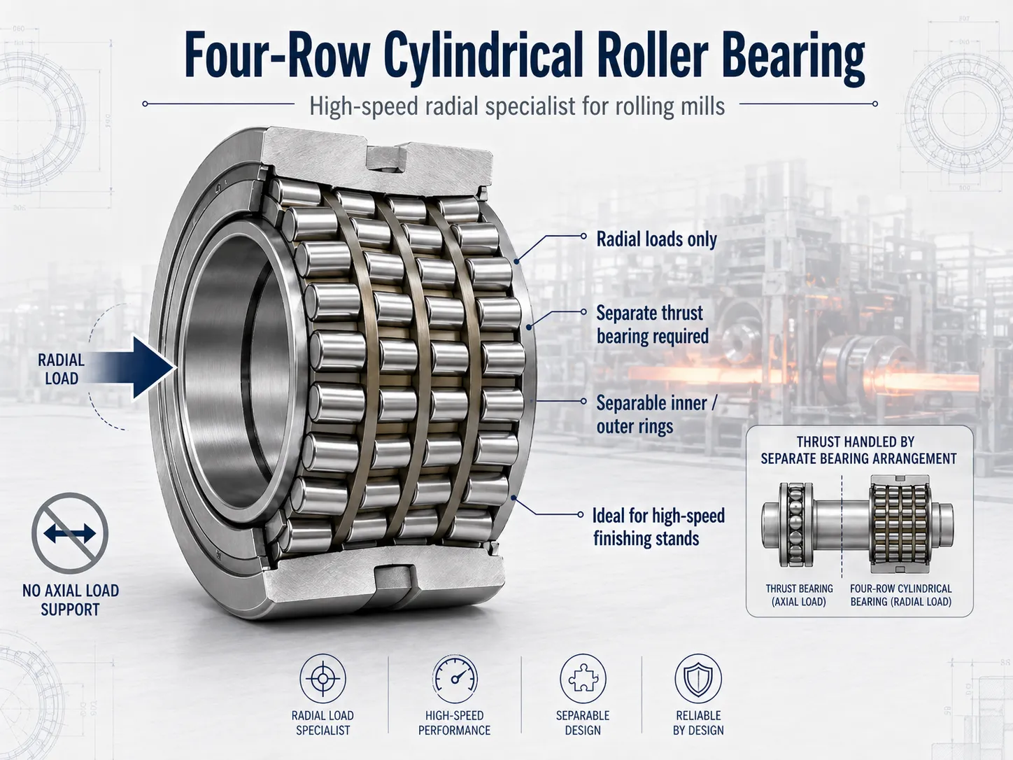
4列円筒ころ軸受は、巨大なラジアル力を非常に高い効率で処理する、その一点のために設計されています。ころが軌道輪と全長にわたって接触する線接触形状は、点接触の代替品と比較して、はるかに大きな表面積に荷重を分散します。本軸受はラジアル荷重専用に設計されており、アキシャル力を管理するためには別体のスラスト軸受との組み合わせが必須となります。ストリップ圧下力が主にラジアルである高速仕上圧延機では、この特化が直接的に長寿命と低発熱に結びつきます。
スラスト軸受の必要性
ラジアル特化には構造上の代償が伴います。円筒ころ軸受は単独ではアキシャル荷重を処理できません。すべての設置において、圧延中に発生するアキシャル力を処理するため、補助軸受、典型的には深溝玉軸受またはアンギュラ玉軸受が必要となります。これによりコンポーネント数が増え、ハウジングの複雑さが増し、保全上のチェックポイントも追加されます。アキシャル荷重が円筒ころ軸受に伝達されて早期故障を引き起こすことを防ぐ設計が、システムレベルで求められます。
速度性能と分離可能設計
円筒ころ軸受は高速運転において真に優れた性能を発揮します。低摩擦特性は急速な加減速サイクルを支えるため、生産性がスループット速度に依存する仕上圧延機では実質的な利点となります。また、内輪と外輪を分離可能な設計により、円筒ころ軸受は保全面でも極めて実用的です。技術者はアセンブリ全体を分解することなく、個々の構成部品を取り外し、検査し、清掃できます。SKFが2000年代初頭に投入したExplorer形円筒ころ軸受シリーズは、従来標準と比較して最大3倍の使用寿命を実現します。この向上は、よりクリーンな鋼、洗練された熱処理、より厳しい製造公差、改善された表面仕上げによってもたらされたものです(SKF Evolution、2009年)。
円筒設計が限界に達する領域
中核的な制約はアキシャル荷重への非対応です。ロールシフト、ビレットのキャンバー、方向性荷重変化など、相当のアキシャル力を受ける軸受は、円筒設計のみに依存することはできません。補助スラスト装置が必要となり、システムの複雑さと保全工数が増します。円筒ころ軸受はまた、圧延ライン全体での適応性が低く、速度が支配的な仕上ポジションにおいてこそ優れた性能を示します。
円すいころ軸受と円筒ころ軸受は項目別にどう比較されますか?
円筒ころ軸受と円すいころ軸受の違いは、それぞれが力の方向をどのように処理するかに帰着します。圧延機の稼働率を決定する変数にわたる比較は以下の通りです。
| 項目 | 4列円すいころ軸受 | 4列円筒ころ軸受 |
|---|---|---|
| 荷重タイプ | ラジアル+アキシャル複合(自己完結型) | ラジアルのみ – 別体スラスト軸受が必要 |
| 最適なミル位置 | 粗圧延機・中間圧延機 | 高速仕上圧延機 |
| ロール交換速度 | 速い(すきまばめ取付、引き抜き工具不要) | 速い(分離可能な内輪/外輪) |
| ハウジングの複雑さ | 堅牢なチョック設計、精密な予圧設定 | より許容度の高いハウジング形状 |
| 速度許容性 | 中程度(つば-ころ接触が高RPMで発熱) | 優秀(低摩擦、急速な加減速) |
| アキシャル荷重処理 | 内蔵、補助軸受不要 | 補助のアンギュラ玉軸受または深溝玉軸受が必要 |
| 最適用途 | ロールシフト、ビレット進入力、複合荷重キャンペーン | 高スループットのストリップ仕上、速度駆動型操業 |
荷重方向:根本的な分岐点
最も重要な違いは荷重方向の管理です。4列円すいころ軸受は、ラジアル荷重とアキシャル荷重の複合を単一アセンブリ内で処理します。円すい設計は接触形状そのものから内部にアキシャル成分を発生させるため、軸受はスラストに抵抗するのではなく、自然にスラストを受け入れます。円筒ころ軸受は卓越したラジアル容量を提供しますが、いかなるアキシャル力に対しても別体のスラスト軸受配置が必要です。クロスローディングを防ぐため、その追加された複雑さは慎重に設計しなければなりません。
速度:各構造が真価を発揮する領域
円筒ころ軸受は、速度が支配的な用途で改めて優位性を示します。線接触形状と高RPMでの低発熱量により、仕上圧延機スタンドにおける第一選択となっています。円すいころ軸受は、高速領域においてつば-ころ界面で内部すべりが増え、追加の発熱が発生するため、性能上限が制約されます。一方で、円すい設計は汎用性で勝ります。より広い速度・荷重範囲にわたって有能に動作するため、圧延ライン全体を通じて適応性の高い選択肢となります。
取付および保全の複雑さ
ロール交換のサイクルタイムは、見落とされがちな生産性のレバーです。円筒ころ軸受は内輪と外輪の分離が可能で、ロール取り外しを簡素化します。4列円すいころ軸受は取付時に精密な予圧設定を要します。手順が増える反面、軸受の使用寿命を通じて一貫した性能を担保します。この予圧要件はハウジング設計にも影響します。円すいころ軸受はより堅牢で慎重に公差設計されたチョックを必要とし、円筒構成はそれより許容度の高いハウジング形状を許します。
ロールネック軸受の使用寿命を左右する他の要因は何ですか?
正しい構造の選択は、最初の判断に過ぎません。ロールネック軸受から最大限の性能を引き出せるかは、製造品質、潤滑管理、表面健全性、状態監視に同等に依存します。
製造の一貫性
高応力の圧延環境では、軸受間のばらつきは稼働率に対する直接的な脅威となります。認証された製造プロセスは、厳密な寸法公差と冶金的な一貫性を担保します。これは、軸受が1時間に数千回の極端なラジアル荷重サイクルを受ける際に決定的に重要です。一貫した内部形状は、転動体間の荷重分布に直接影響します。したがって、認証された製造はプレミアムな付加要素ではなく、基本要件として位置づけられます。
ポジション別の潤滑戦略
高速で稼働する仕上圧延機の用途は、熱負荷下で安定した潤滑膜を維持するオイルミストまたは循環油システムから恩恵を受けます。粗圧延機のワークロール位置は、その低い回転速度ゆえに、グリース潤滑の開放型設計でも一般に許容されます。円すい・円筒のいずれの設計も、ポジションに合致した潤滑戦略に依存します。圧延ライン全体に通用する万能の答えは存在しません。
表面仕上げと予知保全監視
軌道輪の表面仕上げは、起動過渡期に転動体と軌道輪の間で流体潤滑膜がどれだけ効果的に形成されるかを直接左右します。起動過渡期は、金属同士の接触に対して最も脆弱な期間です。ロールネックの温度と振動シグネチャの監視は、軌道輪疲労、潤滑剤劣化、進行中のミスアライメントの早期警告を提供します。 私たちが支援する圧延機のお客様の現場全般において、温度トレンド分析は潤滑不良が壊滅的なスポーリングへとエスカレートする前に、それを一貫して検出します。これらの戦略は、構成にかかわらず両方の軸受タイプに等しく適用されます。
ミルスタンドに適した軸受の選定
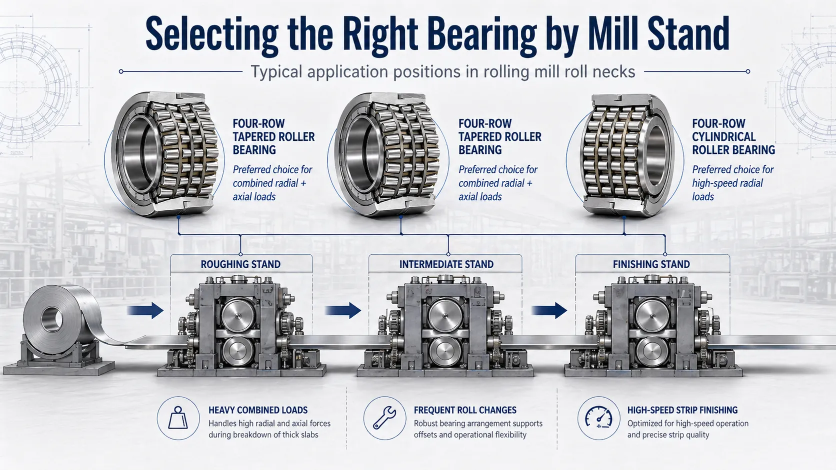
判断は荷重プロファイルと速度要件に帰着します。4列円すいころ軸受は、ワークロールがラジアルとアキシャルの複合荷重を受け、頻繁な交換が要求される場面で真価を発揮します。これはまさに方向性のある力が常時作用する、ほとんどの粗圧延機および中間圧延機の状況です。4列円筒ころ軸受は、仕上圧延機が必要とするラジアル精度と速度能力を提供します。最大スループット速度を得るための代償として、補助スラスト軸受配置という追加の複雑さを受け入れます。
どちらの構造も普遍的に優れているわけではありません。正しい軸受は、特定のミルスタンドの荷重プロファイル、速度域、操業リズムに合致するものです。選定にあたっては、定格容量を実際の稼働率に変換するための潤滑、取付、監視のプロトコルも考慮しなければなりません。
よくあるご質問
Q: 4列円筒ころ軸受はアキシャル荷重を少しでも処理できるのですか?
いいえ。4列円筒ころ軸受はラジアル荷重専用に設計されています。線接触形状によって巨大なラジアル力を効率的に分散しますが、ころそのものはアキシャル方向の動きに抵抗できません。すべての設置において、補助のスラスト軸受、典型的には深溝玉軸受またはアンギュラ玉軸受の組合せが必要となり、ロールシフト、ビレットのキャンバー、方向性荷重変化に伴うアキシャル力を吸収します。アキシャル荷重が円筒ころ軸受に伝達されると、軌道輪の急速な損傷と早期故障を招きます。
Q: 粗圧延機で円筒ころ軸受が機能する場合はあるのですか?
ごく稀であり、スタンド固有の設計でアキシャル荷重を別途処理できる場合に限られます。粗圧延機は通常、ビレット進入、ロールシフト、リバース運転に伴う相当の方向性荷重を受けるため、アキシャル容量を統合した円すい形状が有利です。粗圧延ポジションでの円筒構成には、堅牢な補助スラスト軸受配置、アキシャル荷重を隔離する慎重なハウジング設計、クロスローディングを防ぐ規律ある保全が必要です。粗圧延機の低RPMで得られる速度面のわずかな利得に対して、システムの複雑さは見合わないため、ほとんどの操業者はこの位置に4列円すい設計を標準採用しています。
Q: 円すいロールネック軸受でらせん油溝が重要なのはなぜですか?
軸受ボアに加工されたらせん油溝は、ロールネッククリープ、すなわち内輪とシャフトの間でフレッチング摩耗を生じさせる微小すべり現象を防止します。この溝はボアとシャフト界面における潤滑を一定に保ち、フレッチングを引き起こす条件そのものを断ち切ります。溝がなければ、内輪は荷重サイクルのもとで徐々にシャフトに対して移動し、時間とともに両面を損傷していきます。良質な4列円すい設計では、らせん油溝が標準で備わっています。低品質な代替品ではしばしば省略されており、その省略は使用中に加速摩耗として顕在化します。
Q: 予圧設定は円すいころ軸受の使用寿命にどのように影響するのですか?
予圧は、4列すべての転動体への荷重分布を決定します。予圧が不足すると内部の遊びによって方向転換時に転動体が軌道輪上ですべり、局所摩耗を発生させます。予圧が過大であれば摩擦と熱が増し、潤滑剤劣化と軌道輪疲労が加速します。軸受メーカーの仕様に従って取付時に正しく設定された予圧は、荷重を均等に分布させ、予測可能な熱挙動をもたらします。ロールネックチョックは、熱サイクルとロール交換を経てもその予圧を維持できるよう設計されなければなりません。これが、円すい構成が円筒構成よりも厳しいチョック公差を要求する理由の一つです。
Q: 同一の圧延ラインで両タイプの軸受を併用するのは一般的なのですか?
はい。最新の熱間圧延機の多くは、粗圧延機および中間圧延機に4列円すいころ軸受を、仕上圧延機に4列円筒ころ軸受を採用しています。これらの構造は競合関係にはありません。それぞれが異なる課題を解決するものであり、適切に設計された圧延ラインは、各構造を最も適合する位置に配置します。2種類の異なる軸受を調達することになるため、調達上の複雑さは増します。しかし、整備間隔の延長と仕上圧延機のスループット向上という運用上の便益は、ほとんどの操業者にとって在庫管理上のオーバーヘッドを十分に上回ります。
重要ポイント
- 複合荷重要件と高頻度のロール交換を伴う粗圧延機・中間圧延機には、4列円すいころ軸受を充ててください。
- 高速かつラジアル荷重が支配的な仕上操業には、円筒ころ軸受を選定してください。
- いずれの軸受タイプも、定格寿命を発揮するには適切な予圧、潤滑、ハウジング設計が不可欠です。
- 4列円すいころ軸受の利点(自己完結型の荷重処理、すきまばめ取付、らせん油溝)は、一貫した製造品質があって初めて実現します。
- 軸受選定はシステムレベルの判断として扱ってください。荷重プロファイル、速度、潤滑、ハウジング設計のすべてが整合してから決定する必要があります。
すべての圧延機軸受タイプの包括的な概要と、選定および保全のガイダンスについては、圧延機軸受の決定版ガイドをご覧ください。圧延機軸受の製品ラインナップ全体をご確認いただくか、お客様の特定のミル構成に関する技術コンサルテーションについては、エンジニアリングチームへお問い合わせください。


